Fiber Splicing Tutorial
1. Intro
These instructions assume only the required tools are used, and minimal precautions taken; no assumptions about safety equipment or convenient tools.
There are 7 procedures to perform in the splicing process; roughly in the following order:
- setup
- strip cable to bare fiber
- cleave bare fiber
- fuse
- test
- apply heat to shrink sleeve and tube
- clean up
Procedures 2 and 3 will be performed twice; once for each of the two cables. However, one side will need to have more outer jacket stripped off to make room for the shrink sleeve; to move it out of the splicer. The side on which the sleeve will be is refered to as Side With Sleeve (SWS), and the other as Side WithOut Sleeve (SWOS). Note that the sequence will be strip SWS, cleave SWS, position SWS in splicer, AND THEN strip SWOS, cleave SWOS and position SWOS in splicer. That sequence minimizes the risks of mishandling each cable, which could result in one or both of 1) a fiber splinter and 2) breaking the bare fiber; either of which could require starting the process over for that cable since even if the bare fiber did not break, if it has been cleaved, poking any surface could ruin the cut.
During procedure 4, the fibers may need to be repositioned multiple times to align the fiber correctly. This is because, as noted in the fiber safety page (detail 3 to consider), the cable is curved; making this part challenging since the cable needs to be positioned straight and precisely.
Procedure 5 is performed before 6 since it would be a waste of time and resources to shrink the shrink sleeve and the shrink tube if the splice needs to be redone.
2. Steps with pictures
Bellow are pictures taken through out the splicing process. (the ordering numbers come from the detailed list in the next section)
- Stripping the outer jacket of SWS:
- Stripping the inner jacket of SWS:
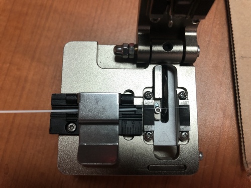
- Positioning the stripped SWS in the cleaver:
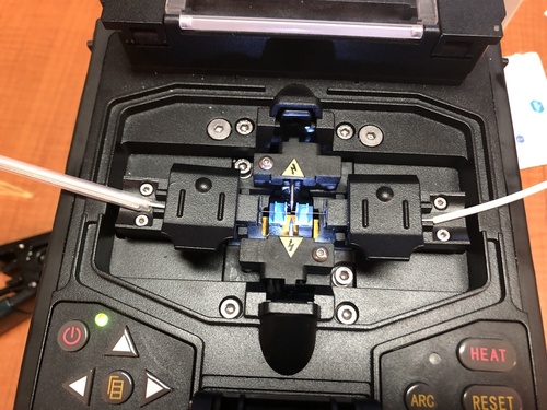
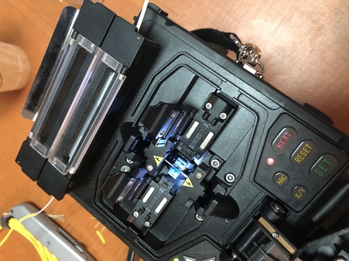
- Positioning the cleaved SWS in the splicer:

16-17) Stripping the outer and inner jackets of SWOS:
- Positioning the cleaved SWOS in the splicer:
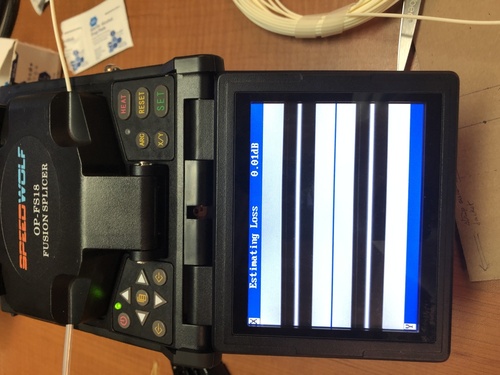
- Read splicer screen to view the quality of the splice and an estimate of signal loss:
- Test splice:

- Place shrink sleeve over the fused, bare fiber and move the whole to the splicer's heating compartment to shrink the sleeve:
- Verify that the sleeve has in fact shrunk (may need to heat 1-3 times):
The result:
3. Detailed list of steps
3.1 Prep
-
prepare all the equipment required; includes tools and any PPE.
-
cut shrink tube (20cm).
-
prepare shrink sleeve.
-
mark location to cut on cable from each side.
-
slide shrink tube down either cable.
3.2 Begin Process
-
Take a cable from either side; this cable will be the side with the shrink sleeve (SWS), the other will be the side with out the sleeve (SWOS).
-
Strip outer jacket of SWS (12cm) and cut kevlar.
-
Slide shrink sleeve over inner jacket of SWS.
-
Strip inner jacket of SWS (2cm) into sharps container.
-
Strip cladding of SWS into sharps container and apply alcohol pad.
-
Cleave SWS.
-
Use tweezers to pick up fiber fragment and drop into sharps container; verify that the segment was indeed in the tweezers all the way to the sharps container, and that it fell in the container before putting the tweezers down.
-
Position SWS in fusion splicer.
-
Use tape to clean any potential glass pieces around and between cleaver and sharps container (if they are not moved before cleaving the other side, this can be done after the second cable is cleaved).
-
Take SWOS.
-
Strip outer jacket of SWOS (5cm) and cut kevlar.
-
Strip inner jacket of SWOS (2cm).
-
Strip cladding of SWOS and apply alcohol pad.
-
Cleave SWOS.
-
Use tweezers to pick up fiber fragment and drop into sharps container; verify that the segment was indeed in the tweezer all the way to the sharps container, and that it fell in the container before putting the tweezers down.
-
Clamp SWOS and position it in fusion splicer (clamp to reduce movement when removing the splicer clamp; due to cable curve).
-
Use tape to clean any potential glass pieces around and between cleaver and sharps container.
-
Fuse cables.
-
Connect cable ends to testing devices and test signal loss.
-
Carefully release each cable from splicer clamps.
-
Slide shrink sleeve over exposed fiber and place in splicer's heating compartment; sleeve should cover each side roughly 3cm from joint.
-
Heat 2-3 times.
-
Slide shrink tube over shrunk sleeve; the shrink tube must leave no inner jacket exposed.
-
Shrink shrink tube with lighter while adjusting grip to ensure the shrink tube cools straight; may consider using solder clamps for this step.
3.3 Clean and pack up
-
Use tape to clean each piece of equipment and put them back in toolbox
-
Fold tape in half, sticky side in, to trap any potential glass pieces.
-
Dispose of tape and pack up the rest of equipment.
4. Template
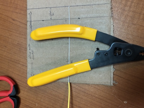
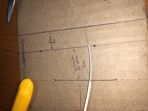
In order to strip jackets quickly and precisely the installer should make a template, such as the one shown bellow.
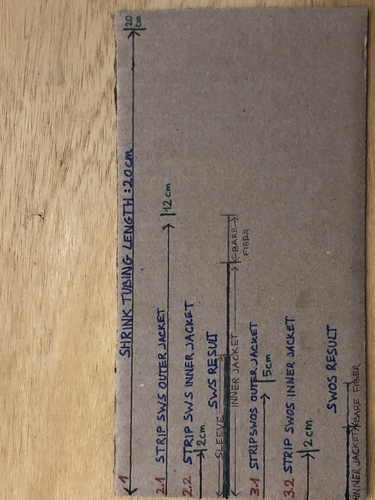
Note that the template in the picture is crowded to illustrate the instructions in section 3; a color coded stick may be easier to work with.
Stick template example (1 dash = 1cm):
< - - - -0- - - - >< -1- >< -2- - >< - - -3- - - - >< - - - -4- - - - >
0: no color -> 8cm; Space for palm of hand.
1: green -> 2cm; Strip inner jacket of both SWS and SWOS.
2: white -> 3cm; green + white = 5cm to strip SWOS outer jacket.
3: yellow -> 7cm; green + white + yellow = 12cm to strip SWS outer jacket.
4: black -> 8cm; green + white + yellow + black = 20cm to cut shrink tubing.
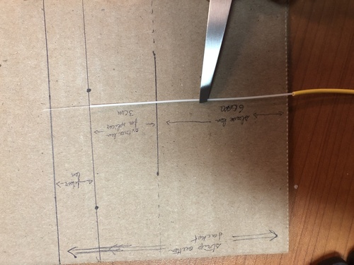
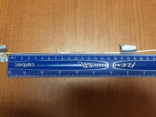
The following pictures show the measurements used to determine the lengths. Note that template lengths are longer to leave ample room for errors.
The pictures show that:
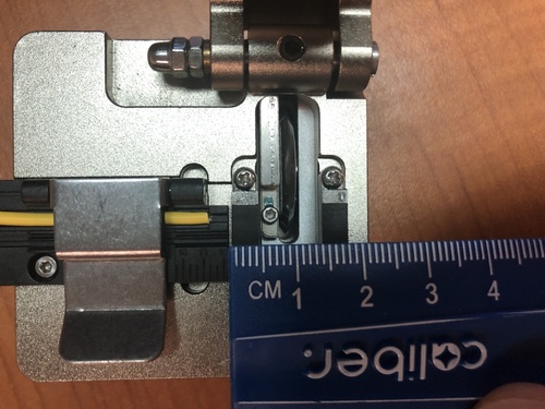
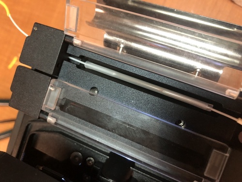
- The outer edges of the cleaver pads are 1.8cm apart; this is the minimum length of bare fiber required for proper grip to cleave.
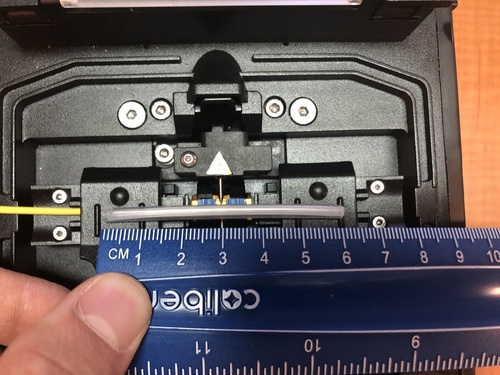
- The cleaver will leave about 1.5cm of bare fiber on each cable -> the 6cm shrink sleeve will cover about 3cm of bare fiber and 3cm of inner jacket.
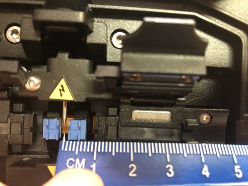
- The shrink sleeve on SWS needs to be >4cm away from the splicer needles to clear the clamp (includes 1.5cm of bare fiber) -> 10cm of inner jacket on top of the 1.5cm of bare fiber.
- The resulting gap (shown in the result picture in section 2), from outer jacket to outer jacket, which needs to be wrapped in shrink tubing is about 16cm -> cut 20cm of unshrunk shrink tubing.