OSPF Configuration Guide
This guide contains in-depth parameters on Layer 2 and 3 configurations. This guide is not meant to be a comprehensive guide on overall networking, but an extension of existing concepts to solve Mesh-specific problems.
It is encouraged that you familiarize yourself with the NYC Mesh OSPF Routing Methodology to better understand the concepts and techniques in this page prior to putting these methods into practice.
What is the "Mesh bridge"?
On the Mesh, almost all routers have a "mesh bridge", which is an isolated, virtualized switch that connects home/apartment routers and radios together. All of the wireless radios on the NYC Mesh network are configured to operate in "bridge" mode, which means that the routers themselves are responsible for sending and routing packets to their neighbors which will be visible through the connected radios. As detailed in our routing methodology, this bridge is set with a standardized cost of 10 across the network to facilitate simple deployment of new equipment and ease-of-use for the volunteers that support and maintain it.
To see what OSPF interfaces are configured on a Mikrotik router on ROS6, use the routing ospf interface print command.
[admin@nycmesh-8300-omni] > routing ospf interface print
Flags: X - disabled, I - inactive, D - dynamic, P - passive
 #    INTERFACE    COST PRIORITY NETWORK-TYPE   AUTHENTICATION AUTHENTICATION-KEY
 0    mesh           10        1 ptmp           none
 1    wds           100        1 ptmp           none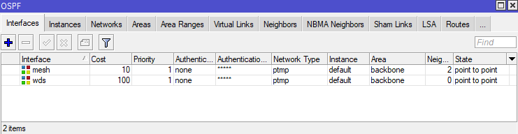
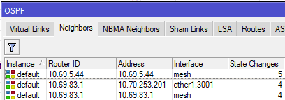
Adjacent routers in an OSPF area see each other as "neighbors", and each router is aware of all other routers in its area. On Mikrotik routers, you can see the OSPF neighbors by using the routing ospf neighbor print command.
[admin@nycmesh-8300-omni] > routing ospf neighbor print
 0 instance=default router-id=10.69.83.1 address=10.69.83.1 interface=mesh
   priority=1 dr-address=0.0.0.0 backup-dr-address=0.0.0.0 state="Full"
   state-changes=4 ls-retransmits=0 ls-requests=0 db-summaries=0
   adjacency=4h39m31s

 1 instance=default router-id=10.69.5.44 address=10.69.5.44 interface=mesh
   priority=1 dr-address=0.0.0.0 backup-dr-address=0.0.0.0 state="Full"
   state-changes=5 ls-retransmits=0 ls-requests=0 db-summaries=0
   adjacency=4h39m38s
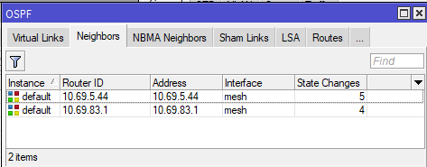
In the above example, we see that this router has two neighbors, 10.69.5.44 and 10.69.83.1, and both are on the "mesh" interface which has a cost of 10.
Why would you need a non-standard OSPF interface?
Sometimes the need will arise that a particular link should have a different cost than the mesh bridge standard, such as:
- Links between hubs to dictate preferred routes based on wireless link speed, quality, and rain resiliency
- Forcing a preferred route at a node over a backup route
- Ensuring new nodes and hubs with multiple links do not inadvertently become primary exit routes for higher-capacity hubs
- Utilizing BFD for faster failover on links with poor rain performance
The solution to this is to create a new dedicated OSPF interface (which is not on the mesh bridge) between two routers with a point-to-point address space, and a non-standard cost.
Considerations for Configuration
The implementation of an OSPF interface depends on two factors:
- If the link is Point-to-Point (two radios that only connect to each other, or a wired link), or Point-to-Multipoint (one radio connected to an access point that serves one or more other radios)
- Whether there is a switch between the router and the radio, and if it is managed or unmanaged
The following table shows the most common link types and their requirements for OSPF configuration. Note that each end of a link may have different characteristics, and therefore different requirements. Some routers and radios support VLAN tagging on egress; for the purposes of simplicity and conformity to NYC Mesh standards, VLAN interfaces should be used as follows
| Link Type | Connection to Router | VLAN Interface Required | Switch port egress |
| PtP | Direct | No | N/A |
| PtP | Through managed switch | Yes* | Untagged |
| PtMP |
Direct or through managed switch | Yes (both ends) | Tagged |
| Any | Through unmanaged (dumb) switch | Yes (both ends) | N/A (Tagged) |
Sidebar: nuances of VLAN configurations with Mikrotik and Ubiquiti Hardware
Before describing implementation steps, it's important to understand how VLANs work on switch ports; in all PtMP links, or if either end of the link has a switch between the radio and router (extremely common at NYC Mesh hubs), you will need to create VLAN interfaces on the router and instruct the switch where to send the VLAN-tagged traffic.
The first concept to understand is Ingress vs Egress Traffic
- Ingress traffic is traffic entering a physical or virtual port on a device, which is then passed to other interfaces or bridges on the local device
- Egress traffic is traffic exiting a physical or virtual port on the local device to a another connected device
- For the purposes of routing and switching tables, an ingress port is the port that traffic enters the device through, and the egress port is the port that it exits through
The second concept is a VLAN interface on Mikrotik devices, which is a virtual interface associated with a physical port that "listens for" tagged traffic through the physical port only with the specified VLAN ID, and automatically untags that traffic before passing it onto the bridge or OSPF instance. This also works in reverse; untagged traffic on the bridge or OSPF Interface can "enter" the vlan interface and is tagged before egress out the physical port.
Multiple VLAN Interfaces on a single physical router port
The third concept is VLAN behavior on switch ports. On a managed switch, generally you must define what ports are allowed to pass traffic with specific VLAN tags in the VLAN table, but you also have the ability to add, modify, and remove tags on traffic entering and exiting the switch port, which will be key for configuration later in this guide. Mikrotik and Ubiquiti use similar terminology on their switches:
- for Mikrotik switches, bridge vlan-filtering=yes must be enabled on the bridge otherwise tagged traffic will be able to ingress/egress through any port on the bridge
- Switch ports set as Tagged for a VLAN are allowed to pass both ingress and egress tagged traffic with the specified VLAN, but do not modify the tag. These are commonly used for Trunk ports.
- Switch ports set as Untagged for a VLAN will accept the tagged ingress traffic from the switch chip and strip the specified VLAN ID on egress.
- On Ubiquiti Edgepoint S16 switches, untagged ingress traffic on the port will be automatically tagged with the VLAN ID specified
- On Mikrotik devices, untagged ingress is usually not automatically tagged; this can be accomplished with the "PVID" value on the bridge port vlan setting
- Note that you must specify at least 2 ports per VLAN, otherwise the traffic will be dropped by the switch
[admin@nycmesh-219-netpower16p] /interface bridge vlan> print
Flags: X - disabled, D - dynamic
 #   BRIDGE           VLAN-IDS  CURRENT-TAGGED          CURRENT-UNTAGGED
 0   ;;; lbelr to PH
     bridge           1072      ether1
                                ether15
 1   bridge           99        ether1                  sfp-sfpplus1
 2   ;;; Revere 7985 (lbe)
     bridge           2301      ether1
                                ether14
 3   ;;; mgmt
     bridge           50        ether1
                                ether15
                                ether13
 4   ;;; af60 to Vernon
     bridge           1092      ether1
ether13 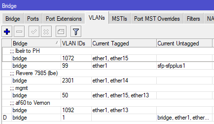
Bridge VLAN table on a Mikrotik Netpower 16P
Implementation scenarios with directly-connected antennas
The following section details the configuration steps for the scenarios listed in the table above. While this will not cover every scenario you may find, it should give you the knowledge needed to create links of varying complexity.
Important Notes: Making changes to default OSPF costs can have unintended effects, up to and including network-wide outages, and frequently requires modifying Hub configurations. Testing and learning should not be done in production environments. Before making changes to NYC Mesh routing configurations, discuss in our Slack #architecture channel and/or applicable hub channel and check the NYC Mesh Node Explorer tool for current routing information.
Before setting up secondary links, double-check that the appropriate Bridge Filters are enabled on the local router. A misconfigured or disabled Mesh Bridge Filter may result in 0-cost links between neighboring nodes and Hubs, risking major network congestion or outages.
When implementing changes in production, be mindful of order of operations and availability of backup routes; removing a remote interface from the mesh bridge will cause the link to drop and you may lose remote access to the router if there is not another OSPF neighbor visible to the router
At a high level, this configuration is simpler than it sounds.
- Reserve a point-to-point address space (/31 for Mikrotik, /30 for Juniper) for the two routers to connect
- If the data will traverse through a switch or an Access Point/PtMP antenna on either end, create VLAN interfaces on both routers for tagged traffic to traverse the link
- On the non-AP side, create a second VLAN interface for management access to the radio, added to the mesh bridge, and set the radio's management VLAN to match
- Add the IP addresses from the point-to-point address space to the interfaces on both ends
- Add the physical (for PtP with no switches) or VLAN interfaces as OSPF interfaces on the routers as "PTMP" network type with bfd enabled
- Add the point-to-point OSPF address space to the backbone
- On the non-AP side(s), remove/disable the physical interface from the Mesh bridge so data can only traverse through the new OSPF interface
- If data will traverse through a switch, update the switch vlan table to allow tagged traffic to pass
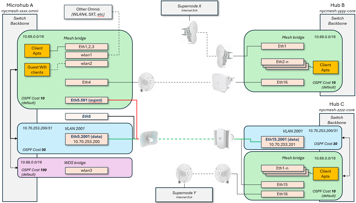
This diagram shows how this would look logically for a Microhub on the left to connect to two different Hubs with separate exits; this grants automatic failover for Microhub A in the event that the primary link, or Hub B / Supernode X goes down.
Scenario 1: Point to Point with directly-attached antennas
Router A > untagged > Antenna A <> Antenna B < untagged < Router B
This is the simplest configuration, as each end of the link has an antenna (or hardwire) plugged directly into the routers on each end. Because all traffic through the link should be on the new interface, we do not need to create any VLAN interfaces; the physical port itself can be removed from the Mesh bridge and added as a standalone OSPF interface with adjusted cost.
- If performing this on a remote site, ensure the link being adjusted is not a single point of failure before proceeding
- Reserve an unused /31 IP range to be used for the OSPF network (ask in the #architecture channel for access to the IP ranges sheet for more information on this)
- For this example, I will use 10.70.253.200/31
- If one or both of the routers is running Juniper OS, you will need a /30 reservation
- On each router, add the reserved IPs and network to the appropriate interfaces
RouterA: /ip address add address=10.70.253.200 network=10.70.253.201 interface=ether1
RouterB: /ip address add address=10.70.253.201 network=10.70.253.200 interface=ether5
You can verify they were added correctly with /ip address print
[admin@nycmesh-8300-omni] > ip address print Flags: X - disabled, I - invalid, D - dynamic # ADDRESS NETWORK INTERFACE 0 10.104.27.1/26 10.104.27.0 mesh 1 10.69.83.0/16 10.69.0.0 mesh 2 10.68.83.0/16 10.68.0.0 wds 3 10.70.253.200/32 10.70.253.201 ether1 - On each router, add the physical port as an OSPF interface with the correct cost, set for "PTMP", and enable BFD. For this example, I will use cost 9.
You can verify they were added correctly with /routing ospf interface printRouterA: /routing ospf interface add cost=9 interface=ether1 network-type=ptmp use-bfd=yes RouterB: /routing ospf interface add cost=9 interface=ether5 network-type=ptmp use-bfd=yes
[admin@nycmesh-8300-omni] > routing ospf interface print Flags: X - disabled, I - inactive, D - dynamic, P - passive # INTERFACE COST PRIORITY NETWORK-TYPE AUTHENTICATION AUTHENTICATION-KEY 0 mesh 10 1 ptmp none 1 wds 100 1 ptmp none 2 ether1 9 1 ptmp none - On each router, add the OSPF Network so the OSPF interface is routable. Note that this command is identical on both ends.
You can verify they were added correctly with /routing ospf network printRouterA: /routing ospf network add area=backbone network=10.70.253.200/31 RouterB: /routing ospf network add area=backbone network=10.70.253.200/31
[admin@nycmesh-8300-omni] > routing ospf network print Flags: X - disabled, I - invalid # NETWORK AREA 0 10.69.0.0/16 backbone 1 10.68.0.0/16 backbone 2 10.70.253.200/31 backbone - On each router, remove the PtP interface from the Mesh Bridge. This should be done on the remote router first, as you will lose connectivity to the remote device until the local device is updated and the neighbors are re-established
You can verify this is set correctly with /interface bridge port print. For 0 - ether1, the "X" indicates the port is disabledRouter B: /interface bridge port set 4 disabled=yes Router A: /interface bridge port set 0 disabled=yes
[admin@nycmesh-8300-omni] > interface bridge port print; Flags: X - disabled, I - inactive, D - dynamic, H - hw-offload # INTERFACE BRIDGE HW PVID PR PATH-COST INTERNA... HORIZON 0 XI ether1 mesh 1 0x 10 10 none 1 I ether2 mesh no 1 0x 10 10 none 2 I ether3 mesh no 1 0x 10 10 none 3 I ether4 mesh no 1 0x 10 10 none 4 I ether5 mesh no 1 0x 10 10 none 5 I wlan1 mesh 1 0x 10 10 none 6 I wlan2 mesh 1 0x 10 10 none 7 I wlan4 mesh 1 0x 10 10 none 8 I wlan3 wds 1 0x 10 10 none 9 dynamic wds yes 1 0x 100 100 none - Once the bridge ports are disabled on both ends, the OSPF link will activate and establish adjacency; you can validate this on either router with /routing ospf neighbor print
[admin@nycmesh-8300-omni] > /routing ospf neighbor print 0 instance=default router-id=10.69.83.1 address=10.70.253.201 interface=ether1 priority=1 dr-address=0.0.0.0 backup-dr-address=0.0.0.0 state="Full" state-changes=9 ls-retransmits=0 ls-requests=0 db-summaries=0 adjacency=6m30s
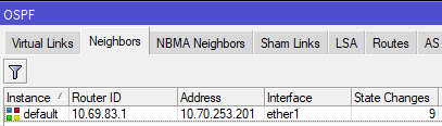
Now we have established a 9-cost OSPF link between the two routers! This cost can be changed at will as the network topology changes in the future.
Scenario 2: Point to Multipoint with directly attached antennas
Router A > tagged > Antenna A <> Access Point B < tagged < Router B
This set up is more complicated, because we need to be able to establish a new OSPF session between Router A and RouterB without impacting its existing mesh interface neighbors that are also connected to Access Point B. Unlike the previous example, we need a way for RouterB to know to only send RouterA's traffic to the new OSPF interface, but leave all the other traffic on the default mesh interface.
This is where VLAN interfaces come into play - tagging the traffic with a VLAN ID will allow the traffic to be routed correctly. In this case, we will only be removing the physical port from the mesh bridge on Router A, detailed below
- Reserve an unused /31 IP range and VLAN ID to be used for the OSPF network (ask in the #architecture channel for access to the IP ranges sheet for more information on this)
- For this example, I will again use 10.70.253.200/31, and VLAN ID 3001
- For this example, I will again use 10.70.253.200/31, and VLAN ID 3001
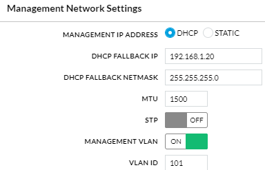
- To ensure we don't lose access to Antenna A's management portal later, create a VLAN interface on RouterA for management and add it to the mesh bridge; this can be any VLAN ID, as long as the same ID isn't being used for management on the other end of the link (because we don't want the two routers to see each other on this vlan). We normally use a X01 VLAN ID related to the physical port. In our case, because the antenna is on ether1, I will use 101.
RouterA: /interface vlan add interface=ether1 name=ether1.101 vlan-id=101 RouterA: /interface bridge port add bridge=mesh interface=ether1.101
- On the antenna, set the Management VLAN ID to match the VLAN you just added and save; you should retain connectivity.

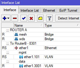
- On each router, create a vlan interface for VLAN 3001 on the physical port the antennas are connected to. We need to use the same VLAN on both ends whenever we traverse through an Access Point to keep this traffic identifiable on both ends of the link. Note that you will not add these interfaces to the mesh bridge.
RouterA: /interface vlan add interface=ether1 name=ether1.3001 vlan-id=3001 RouterB: /interface vlan add interface=ether5 name=ether1.3001 vlan-id=3001
- On each router, add the reserved IPs and network to the appropriate VLAN 3001 interfaces
RouterA: /ip address add address=10.70.253.200 network=10.70.253.201 interface=ether1.3001 RouterB: /ip address add address=10.70.253.201 network=10.70.253.200 interface=ether5.3001You can verify they were added correctly with /ip address print
On each router, add the vlan interface as an OSPF interface with the correct cost, set for "PTMP", and enable BFD. For this example, I will again use cost 9.[admin@nycmesh-8300-omni] > ip address print Flags: X - disabled, I - invalid, D - dynamic # ADDRESS NETWORK INTERFACE 0 10.104.27.1/26 10.104.27.0 mesh 1 10.69.83.0/16 10.69.0.0 mesh 2 10.68.83.0/16 10.68.0.0 wds 3 10.70.253.200/32 10.70.253.201 ether1.3001
You can verify they were added correctly with /routing ospf interface printRouterA: /routing ospf interface add cost=9 interface=ether1.3001 network-type=ptmp use-bfd=yes RouterB: /routing ospf interface add cost=9 interface=ether5.3001 network-type=ptmp use-bfd=yes
[admin@nycmesh-8300-omni] > routing ospf interface print Flags: X - disabled, I - inactive, D - dynamic, P - passive # INTERFACE COST PRIORITY NETWORK-TYPE AUTHENTICATION AUTHENTICATION-KEY 0 mesh 10 1 ptmp none 1 wds 100 1 ptmp none 2 ether1.3001 9 1 ptmp none - On each router, add the OSPF Network so the OSPF interface is routable.
You can verify they were added correctly with /routing ospf network printRouterA: /routing ospf network add area=backbone network=10.70.253.200/31 RouterB: /routing ospf network add area=backbone network=10.70.253.200/31
[admin@nycmesh-8300-omni] > routing ospf network print Flags: X - disabled, I - invalid # NETWORK AREA 0 10.69.0.0/16 backbone 1 10.68.0.0/16 backbone 2 10.70.253.200/31 backbone - At this point, the two routers should establish adjacency on the VLAN interfaces, and if the cost is <10, then traffic will prefer that route.
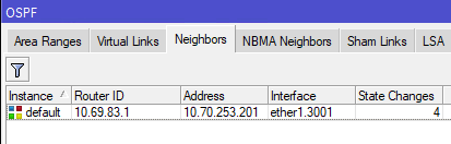
[admin@nycmesh-8300-omni] > /routing ospf neighbor print 0 instance=default router-id=10.69.83.1 address=10.70.253.201 interface=ether1.3001 priority=1 dr-address=0.0.0.0 backup-dr-address=0.0.0.0 state="Full" state-changes=4 ls-retransmits=0 ls-requests=0 db-summaries=0 adjacency=47s 1 instance=default router-id=10.69.83.1 address=10.69.83.1 interface=mesh priority=1 dr-address=0.0.0.0 backup-dr-address=0.0.0.0 state="Full" state-changes=4 ls-retransmits=0 ls-requests=0 db-summaries=0 adjacency=11m26s
- The last step is to remove RouterA's physical port from the mesh bridge, so that traffic can only route through the new VLAN interface you have created. Note that we do not do this step on RouterB, because we want the untagged traffic from other connected antennas to continue to enter the mesh bridge.
Now, OSPF Neighbors will only show the VLAN interface and you are done!Router A: /interface bridge port set 0 disabled=yes

Implementation scenarios where a switch exists between the antennas and routers
Scenario 3: Point to Multipoint with a switch at one or both ends
Router A > tagged > Antenna A <> Access Point B < tagged < Switch B < tagged < Router B
This is one of the most common scenarios you'll encounter in the NYC Mesh network; many multi-member nodes and smaller hubs have a high-capacity 60Ghz radio with a backup 5Ghz radio to the same or a different hub for failover in heavy rain. This scenario is almost identical to Scenario 2, with one important caveat: we have to configure the switch to pass the VLAN traffic to the appropriate switch port.
- Reserve an unused /31 IP range and VLAN ID to be used for the OSPF network (ask in the #architecture channel for access to the IP ranges sheet for more information on this)
- For this example, I will again use 10.70.253.200/31, and VLAN ID 3001
- For this example, I will again use 10.70.253.200/31, and VLAN ID 3001
- To ensure we don't lose access to Antenna A's management portal later, create a VLAN interface on RouterA for management and add it to the mesh bridge; this can be any VLAN ID, as long as the same ID isn't being used for management on the other end of the link. We normally use a X01 VLAN ID related to the physical port. In our case, because the antenna is on ether1, I will use 101.
RouterA: /interface vlan add interface=ether1 name=ether1.101 vlan-id=101 RouterA: /interface bridge port add bridge=mesh interface=ether1.101 - On Antenna A, set the Management VLAN ID to match the VLAN you just added and save; you should retain connectivity.
- On each router, create a vlan interface for VLAN 3001 on the physical port the antenna/switch is connected to. For this example, let's assume that RouterB uses the bond1 interface to connect to the Switch.
RouterA: /interface vlan add interface=ether1 name=ether1.3001 vlan-id=3001 RouterB: /interface vlan add interface=bond1 name=bond1.3001 vlan-id=3001
Note: If there is a bonded/LAG interface (where multiple SFP/ethernet ports are used for uplink), then you should put the vlan interface on the bonded interface - On each router, add the reserved IPs and network to the appropriate VLAN 3001 interfaces
RouterA: /ip address add address=10.70.253.200 network=10.70.253.201 interface=ether1.3001 RouterB: /ip address add address=10.70.253.201 network=10.70.253.200 interface=bond1.3001 - On each router, add the vlan interface as an OSPF interface with the correct cost, set for "PTMP", and enable BFD. For this example, I will again use cost 9.
RouterA: /routing ospf interface add cost=9 interface=ether1.3001 network-type=ptmp use-bfd=yes RouterB: /routing ospf interface add cost=9 interface=bond1.3001 network-type=ptmp use-bfd=yes - On each router, add the OSPF Network so the OSPF interface is routable.
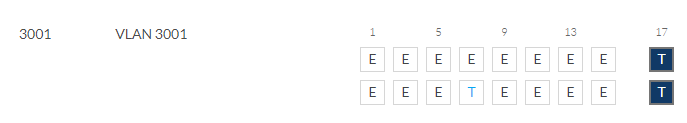
RouterA: /routing ospf network add area=backbone network=10.70.253.200/31 RouterB: /routing ospf network add area=backbone network=10.70.253.200/31 - Here is where we diverge from Scenario 2: we must configure Switch B to pass the tagged traffic to the correct egress port. In this example, let's assume the trunk port to the router is also bond1, and the Access Point is on ether8 on a Mikrotik switch
If not already enabled, we also need to enable vlan-filtering on the SwitchB bridge and ether8.SwitchB: /interface bridge vlan add bridge=bridge tagged=ether8,bond1 vlan-ids=3001
If the switch is a Ubiquiti S16, you would add the VLAN ID and set the trunk and AP ports as Tagged for VLAN 3001, and exclude all other portsSwitchB: /interface bridge set 0 vlan-filtering=yes ether-type=0x8100 pvid=1 frame-types=admit-all SwitchB: /interface bridge port set 7 vlan-filtering=yes ingress-filtering=yes

Note: If there is also a switch between Router A and Antenna A, repeat step 8 on Switch A to allow tagged traffic to pass to the appropriate port
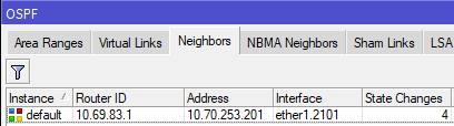
- The two routers should establish adjacency on the VLAN interfaces, and if the cost is <10, then traffic will prefer that route.
[admin@nycmesh-8300-omni] > /routing ospf neighbor print 0 instance=default router-id=10.69.83.1 address=10.70.253.201 interface=ether1.3001 priority=1 dr-address=0.0.0.0 backup-dr-address=0.0.0.0 state="Full" state-changes=4 ls-retransmits=0 ls-requests=0 db-summaries=0 adjacency=47s 1 instance=default router-id=10.69.83.1 address=10.69.83.1 interface=mesh priority=1 dr-address=0.0.0.0 backup-dr-address=0.0.0.0 state="Full" state-changes=4 ls-retransmits=0 ls-requests=0 db-summaries=0 adjacency=11m26s - The last step is to remove RouterA's physical port from the mesh bridge, so that traffic can only route through the new VLAN interface you have created. Note that we do not do this step on RouterB, because we want the untagged traffic from other connected antennas to continue to enter the mesh bridge.
Router A: /interface bridge port set 0 disabled=yes - Now, OSPF Neighbors will only show the VLAN interface and you are done!
Scenario 4: Point to Point with switches on one end
Router A > untagged > Antenna A <> Antenna B < untagged < Switch B < tagged < Router B
This is another common scenarios you'll encounter in the NYC Mesh network, where two hubs connect to each other with dedicated antennas. Similar to Scenario 2, we have to configure the switch to pass the VLAN traffic to the appropriate switch port; but on router A, we do not need a VLAN since the antenna is plugged directly into Router A.
- Reserve an unused /31 IP range to be used for the OSPF network (ask in the #architecture channel for access to the IP ranges sheet for more information on this)
- For this example, I will again use 10.70.253.200/31
- For this example, I will again use 10.70.253.200/31
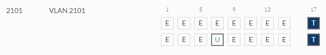
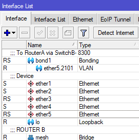
- Create a vlan interface with a VLAN of your choice on the physical port the switch is connected to; if there are switches on both ends of the link, do the same on the other end (the VLANs do not have to be the same, but can be if you choose). For this example, let's assume that RouterB uses the bond1 interface to connect to the Switch, and we will use VLAN 2101.
RouterB: /interface vlan add interface=bond1 name=bond1.2101 vlan-id=2101
Note: If there is a bonded/LAG interface (where multiple SFP/ethernet ports are used for uplink), then you should put the vlan interface on the bonded interface - On each router, add the reserved IPs and network to the appropriate physical or virtual interfaces. Because RouterA connects directly to AntennaA, we add the address to ether1; for RouterB, we use the bond1.2101 interface we just created in step 2.
RouterA: /ip address add address=10.70.253.200 network=10.70.253.201 interface=ether1 RouterB: /ip address add address=10.70.253.201 network=10.70.253.200 interface=bond1.2101 - On each router, add the applicable interface as an OSPF interface with the correct cost, set for "PTMP", and enable BFD. For this example, I will again use cost 9.
RouterA: /routing ospf interface add cost=9 interface=ether1 network-type=ptmp use-bfd=yes RouterB: /routing ospf interface add cost=9 interface=bond1.2101 network-type=ptmp use-bfd=yes - On each router, add the OSPF Network so the OSPF interface is routable.
RouterA: /routing ospf network add area=backbone network=10.70.253.200/31 RouterB: /routing ospf network add area=backbone network=10.70.253.200/31 - Here is where we diverge from Scenario 1 & 3: we must configure Switch B to pass the tagged traffic to the correct egress port and untag it on egress. We again assume the trunk port to the router is also bond1, and AntennaB is on ether8 on a Mikrotik switch. We need to set the trunk port to RouterB as tagged, and the access port to AntennaB as untagged
SwitchB: /interface bridge vlan add bridge=bridge tagged=bond1 untagged=ether8 vlan-ids=2101Additionally, we need to instruct the Mikrotik switch to tag ingress traffic with the appropriate VLAN ID. If not already set, enable vlan-filtering on the switch bridge. Then, on ether8 set the PVID to 2101, enable ingress filtering, and set the port to only allow untagged traffic on ingress (optional, but recommended for security purposes).
If the switch is a Ubiquiti S16, you only need to set the tagged and untagged port, and exclude ether8 from whatever it is currently set as untagged for:SwitchB: /interface bridge set 0 vlan-filtering=yes ether-type=0x8100 pvid=1 frame-types=admit-all SwitchB: /interface bridge port set 7 vlan-filtering=yes pvid=2101 frame-types=admit-only-untagged-and-priority-tagged ingress-filtering=yes
- The last step is to remove RouterA's physical port from the mesh bridge, so that traffic can only route through the new OSPF interface you have created. Note that we do not do this step on RouterB, because we want the untagged traffic from other connected antennas to continue to enter the mesh bridge.
If, however, RouterA also had a switch in between, then you would not remove the interface from the bridge port and instead repeat step 6 on SwitchA.Router A: /interface bridge port set 0 disabled=yes - Now, OSPF Neighbors will only show the VLAN interface and you are done!


No Comments