Brocade Router CLI Notes
Overview
This ICX6610 network switch may be capable of acting as a core router for a large site in the Mesh. However, it does not support Point to Multi Point (P2MP/PTMP) OSPF which is necessary to talk to the rest of the Mesh network
It provides 802.3at PoE+ power to all of its 48 ports (or 24 ports on the ICX6610-24P), has 10 SFP+ 10G ports on the front, 2 QSFP+ 40G ports on the back, and then 2 QSFP+ ports that can only operate as 4x10G SFP+ breakout cables.
The 40G ports can be used to connect a hub to dark fiber running to a data center, which is how the Juniper QFX5100-48S at Grand St is set up. The QSFP+ to 4x 10G SFP+ ports can be used with Direct Attach Cables (DACs) to connect to other rackmount gear, such as a Ubiquiti PON OLT for in-building fiber to the apartment. The SFP+ ports on the front can be used in a similar way to the Mikrotik CCR2004, connecting fiber runs to a roof rack, Mikrotik netPower 16P, Ubiquiti Wave APs, Siklu EtherHaul 8010FX, etc. The PoE ports can be used to power any device compatible with 802.3af/at active PoE, such as "rabbit ear" Ubiquiti AC Mesh Access Points (APs), IP cameras, IP phones, and even Ubiquiti PoE converters to provide passive 24V PoE.
The switch also has advanced L3 functionality and can also perform routing duties. It supports OSPF, DHCP Server, VLANs, and more.
It is configured either with a DB9/RS232/Serial Console Cable (a Cisco cable works), or via SSH. There is also a Web UI with limited functionality.
The switch has an 800MHz PowerPC processor, 512MB RAM, and runs FastIron OS, which is very similar to Cisco's IOS. The latest software update for the ICX6610 as of 2024Q1 was 2020-04-29 with release 08.0.30u. A used ICX6610-48P was purchased off Ebay for $150 in 2024Q1 for Olmsted NN584, its stock serial number is BXK2526J0YG and its stock software was 08.0.30t (from 2019-02-18) with boot monitor 10.1.00T7f5
Initial Setup - Firmware and License
- The original instructions can be found here and here with a Youtube version here
- This initial setup requires a TFTP server to be running, serving the files needed for these steps. Assume for this example that the TFTP server's IP is 10.97.227.164
- Connect the Management RJ45 port in the back of the switch to the network the TFTP server is connected to. Also connect the Console cable and get the
screenorminicomconsole session going, ready to receive printout from the switch while it boots - Connect power while hitting
Bon the console keyboard to interrupt the boot process and enter the Boot Monitor prompt. If the line is filled withbbb, press Enter to clear to get to a new line
ICX Boot Code Version 10.1.00 (grz10100)
Enter 'a' to stop at memory test
Enter 'b' to stop at boot monitor
***** Interrupted by entering 'b' *****
.BOOT INFO: load monitor from boot flash, cksum = 71f1
BOOT INFO: verify flash files.......
Monitor>bbb
Not found in command table, 'bbb'
Monitor>
- Give the switch a static IP on the same network as the TFTP server. In this example, the switch is 10.97.227.165 so it can connect to the TFTP server 10.97.227.164
Monitor>ip address 10.97.227.165
  IP address = 10.97.227.165
  IP subnet mask = 255.255.255.0
Monitor>
- Update the Boot Monitor and the main software using TFTP, first with
copy tftp flash 10.97.227.164 ICX6610-FCX/grz10100.bin bootand then withcopy tftp flash 10.97.227.164 ICX6610-FCX/FCXR08030u.bin primary
Monitor>copy tftp flash 10.97.227.164 ICX6610-FCX/grz10100.bin boot
Loading image from Tftp
............................................Done
Programming boot flash, please wait..
Erasing....
Writing
Done
Monitor>copy tftp flash 10.97.227.164 ICX6610-FCX/FCXR08030u.bin primary
.......................................Done
.Monitor>
- Erase the config (reset to factory defaults) with
factory set-defaultand theny
Monitor>factory set-default
This command will remove configuration and keys detail.
Do you want to continue? (Y/N) y
Done.
Monitor>
- Finally, reboot the switch to apply the fresh software and settings with
reset. This will take a couple minutes.
Monitor>reset
$
ICX Boot Code Version 10.1.00 (grz10100)
Enter 'a' to stop at memory test
Enter 'b' to stop at boot monitor
.BOOT INFO: load monitor from boot flash, cksum = 71f1
BOOT INFO: verify flash files......
BOOT INFO: load image from primary copy...
- After a couple minutes, the console may be printing repeated
TFTP session timed outlines. PressENTERto get past the messages and to a prompt.
PoE Info: PoE module 1 of Unit 1 initialization is done.
TFTP session timed out
TFTP session timed out
TFTP session timed out
ICX6610-48P Router>
- Enter the configuration mode with
enableand thenconfigure terminal. Then disable the DHCP client withip dhcp-client disable
ICX6610-48P Router>
ICX6610-48P Router>enable
No password has been assigned yet...
ICX6610-48P Router#configure terminal
ICX6610-48P Router(config)#TFTP session timed out
ICX6610-48P Router(config)#ip dhcp-client disable
ICX6610-48P Router(config)#
- Now give the switch a static IP address. All ports are VLAN1 by default. Give VLAN1 its own virtual interface, and then assign that virtual interface an IP address (the same as before). Then write the memory to save these settings as permanent
ICX6610-48P Router(config)#vlan 1
ICX6610-48P Router(config-vlan-1)#router-interface ve 1
ICX6610-48P Router(config-vlan-1)#exit
ICX6610-48P Router(config)#interface ve 1
ICX6610-48P Router(config-vif-1)#ip address 10.97.227.165/24
ICX6610-48P Router(config-vif-1)#exit
ICX6610-48P Router(config)#write memory
Write startup-config done.
ICX6610-48P Router(config)#exit
ICX6610-48P Router#
- Disconnect the Ethernet cable from the management port and move it to any of the ports on the front of the switch. Otherwise, the TFTP connection won't work in the next steps
- Now update the PoE module firmware (one per switch, this is not related to the power supplies), again using the TFTP server, with
inline power install-firmware stack-unit 1 tftp 10.97.227.164 ICX6610-FCX/fcx_poeplus_02.1.0.b004.fw
ICX6610-48P Router#inline power install-firmware stack-unit 1 tftp 10.97.227.164 ICX6610-FCX/fcx_poeplus_02.1.0.b004.fw
ICX6610-48P Router#Flash Memory Write (8192 bytes per dot) ...........
 tftp download successful file name = poe-fw
Sending PoE Firmware to Unit 1.
ICX6610-48P Router#
- Use
show logto monitor the update process, which may take 10 minutes.
ICX6610-48P Router#show log
Syslog logging: enabled ( 0 messages dropped, 0 flushes, 0 overruns)
    Buffer logging: level ACDMEINW, 14 messages logged
    level code: A=alert C=critical D=debugging M=emergency E=error
                I=informational N=notification W=warning

Static Log Buffer:
00 days 00h02m39s:I:System: Stack unit 1 POE  Power supply 1  with 748000 mwatts capacity is up
00 days 00h02m39s:I:System: Stack unit 1 POE  Power supply 2  with 748000 mwatts capacity is up

Dynamic Log Buffer (50 lines):
00 days 00h06m00s:I:System: U1-MSG: PoE Info: Firmware Download on slot 1.....40 percent completed.
00 days 00h05m25s:I:System: U1-MSG: PoE Info: Firmware Download on slot 1.....30 percent completed.
- Reboot using
reloadonce the firmware is updated. The switch won't let the reboot occur until the update is complete
ICX6610-48P Router#reload
Are you sure? (enter 'y' or 'n'): Rebooting(0)...
y
 ICX6610-48P Router#*
$
ICX Boot Code Version 10.1.00 (grz10100)
Enter 'a' to stop at memory test
Enter 'b' to stop at boot monitor
- Now get into privileged mode with
enable, then update the serial number in the software to match the license that will be applied next, and reboot
ICX6610-48P Router>enable
No password has been assigned yet...
ICX6610-48P Router#hw pid-prom serial 2ax5o2jk68e
ICX6610-48P Router#hw pid-prom clear-sw-lid
ICX6610-48P Router#reload
Are you sure? (enter 'y' or 'n'): Rebooting(0)...
y
 ICX6610-48P Router#*
$
ICX Boot Code Version 10.1.00 (grz10100)
- Now re-enter the privileged mode and use TFTP to copy over the license files
ICX6610-48P Router>enable
No password has been assigned yet...
ICX6610-48P Router#copy tftp license 10.97.227.164 ICX6610-FCX/1-6610-ports.xml unit 1
ICX6610-48P Router#Flash Memory Write (8192 bytes per dot) .
Copy Software License from TFTP to Flash Done.
ICX6610-48P Router#copy tftp license 10.97.227.164 ICX6610-FCX/2-6610-adv.xml unit 1
ICX6610-48P Router#Flash Memory Write (8192 bytes per dot) .
Copy Software License from TFTP to Flash Done.
copy tftp license 10.97.227.164 ICX6610-FCX/3-6610-macsec.xml unit 1
ICX6610-48P Router#Flash Memory Write (8192 bytes per dot) .
Copy Software License from TFTP to Flash Done.
- Use
show licenseto confirm that the license has been applied and the 10G ports are usable
ICX6610-48P Router#show license
Index    Lic Mode        Lic Name               Lid/Serial No  Lic Type    Status     Lic Period    Lic Capacity
Stack unit 1:
1        Node Lock       ICX6610-10G-LIC-POD    H4CKTH3PLN8    Normal      Active     Unlimited 8
2        Node Lock       ICX6610-ADV-LIC-SW     H4CKTH3PLN8    Normal      Active     Unlimited 1
3        Node Lock       ICX-MACSEC-LIC         H4CKTH3PLN8    Normal      Active     Unlimited 1
ICX6610-48P Router#
- Finally, run
write memoryto save all the settings so far as permanent
ICX6610-48P Router#write memory
ICX6610-48P Router#Flash Memory Write <8192 bytes per dot> .
Copy Done.
ICX6610-48P Router#
Initial Setup - System
- Enable SSH access to the management command line by first generating an RSA keypair. Then create a username and password. Then enable that username and password to allow logins via SSH and the Web UI. Also disable the Telnet server. Then save the settings
- Optionally,
enable aaa consolecan be added to force a password on the console. JohnB skipped this step since the passwords are all placeholders anyway
- Optionally,
ICX6610-48P Router>enable
ICX6610-48P Router#configure terminal
ICX6610-48P Router(config)#crypto key zeroize
RSA Key pair not found
ICX6610-48P Router(config)#crypto key generate rsa modulus 2048
ICX6610-48P Router(config)#
Creating RSA key pair, please wait...
RSA Key pair is successfully created
ICX6610-48P Router(config)#username root password <mesh password here>
ICX6610-48P Router(config)#aaa authentication login default local
ICX6610-48P Router(config)#aaa authentication web default local
ICX6610-48P Router(config)#no telnet server
ICX6610-48P Router(config)#write mem
- To actually connect via SSH, some special arguments need to be passed in to support the key exchange and host key algorithms supported by the switch
-
ssh -oKexAlgorithms=+diffie-hellman-group1-sha1 -oHostKeyAlgorithms=+ssh-rsa root@10.97.227.165 - https://unix.stackexchange.com/questions/402746/ssh-unable-to-negotiate-no-matching-key-exchange-method-found
- https://askubuntu.com/questions/836048/ssh-returns-no-matching-host-key-type-found-their-offer-ssh-dss
-
- The hostname is by default
ICX6610-48P Routeras seen in the first part of every command line. This can be changed withhostname <newname>. For Olmsted, this has been changed tohostname nycmesh-nn584-brocade-poe-switchor possiblyhostname nycmesh-nn584-brocade-core - To configure the switch's DNS server, https://wiki.mesh.nycmesh.net/link/92 shows that
10.10.10.10is the server of choice for the Mesh.
ICX6610-48P Router>enable
ICX6610-48P Router#configure terminal
ICX6610-48P Router(config)#ip dns server-address 10.10.10.10
- TODO: To configure the default route for the switch, the
ip routecommand can be run. But this may conflict with the OSPF routing table according to Olivier
ICX6610-48P Router>enable
ICX6610-48P Router#configure terminal
ICX6610-48P Router(config)#ip route 0.0.0.0/0 10.69.69.69
- To configure NTP, set Daylight Savings to be enabled, pick the time zone, enter the NTP configuration, disable serving NTP to clients, pick the IP addresses of the NTP servers to source from (maximum support for 8 IPs) and then exit and save
- NOTE that
no ntpwill reset the configuration - The IP for NTP is 10.10.10.123
- NOTE that
clock summer-time
clock timezone gmt GMT-05
ntp
disable serve
server 10.10.10.123
exit
- The NTP status can be checked with
show ntp associationsandshow ntp status - To enable SNMPv2 for statistics gathering, run
snmp-server community public ro - To enable optical module monitoring, run the
optical monitorcommand
ICX6610-48P Router>enable
ICX6610-48P Router#configure terminal
ICX6610-48P Router(config)#optical-monitor
Initial Setup - Ports
- To use the 40G ports on the back of the switch, they need to be removed from the switch stacking configuration
- With its factory settings
show runwill showstack-trunklines claiming usage of the 40G ports in module 2 (the last two lines)
stack unit 1
  module 1 icx6610-48-port-management-module
  module 2 icx6610-qsfp-10-port-160g-module
  module 3 icx6610-8-port-10g-dual-mode-module
  stack-trunk 1/2/1 to 1/2/2
  stack-trunk 1/2/6 to 1/2/7
!
- Go into privileged and then configuration mode and remove the
stack-trunksettings, and disable the stack. Then save the settings withwrite mem
ICX6610-48P Router>enable
ICX6610-48P Router#configure terminal
ICX6610-48P Router(config)#stack unit 1
ICX6610-48P Router(config-unit-1)#no stack-trunk 1/2/1 to 1/2/2
ICX6610-48P Router(config-unit-1)#no stack-trunk 1/2/6 to 1/2/7
ICX6610-48P Router(config-unit-1)#stack disable
ICX6610-48P Router(config-unit-1)#exit
ICX6610-48P Router(config)#write mem
- Now use
show runagain to confirm the configuration has changed
ICX6610-48P Router(config)#show run
Current configuration:
!
ver 08.0.30uT7f3
!
stack unit 1st
module 1 icx6610-48p-poe-port-management-module
module 2 icx6610-qsfp-10-port-160g-module
module 3 icx6610-8-port-10g-dual-mode-module
stack disable
!
- Next, configure the 8 SFP+ ports to operate explicitly at 10G speeds with
speed-duplexcommands. The interfaces can all be configured at the same time. Note that if a module is installed that is 1G and not 10G, an error will be shown.- TODO: Unclear if setting
speed-duplex autoinstead ofspeed-duplex 10g-fullwould also work fine. If not, setting the 1G interfaces tospeed-duplex 1000-fullshould work, as per the command reference PDF. Alternatively, theno speed-duplexwill reset the interface to its default settings
- TODO: Unclear if setting
ICX6610-48P Router>enable
ICX6610-48P Router#configure terminal
ICX6610-48P Router(config)#interface ethernet 1/3/1 to 1/3/8
ICX6610-48P Router(config-mif-1/3/1-1/3/8)#speed-duplex 10g-full
INFO: 1/3/3: optics <-> speed mismatch. Replace with SFP+ to enable link.
ICX6610-48P Router(config-mif-1/3/1-1/3/8)#write mem
Write startup-config done.
- Next, configure all 48 RJ45 ports on the switch to have Active 802.3af/at PoE enabled. Otherwise, they will just act as unpowered ports.
ICX6610-48P Router>enable
ICX6610-48P Router#configure terminal
ICX6610-48P Router(config)#interface ethernet 1/1/1 to 1/1/48
ICX6610-48P Router(config-mif-1/1/1-1/1/48)#inline power
ICX6610-48P Router(config-mif-1/1/1-1/1/48)#write mem
- Also, disable legacy PoE as it can accidentally enable and fry devices sometimes, since it's based on resistance over pairs of wires
ICX6610-48P Router>enable
ICX6610-48P Router#configure terminal
ICX6610-48P Router(config)#stack unit 1
ICX6610-48P Router(config-unit-1)#no legacy-inline-power
ICX6610-48P Router(config-unit-1)#write mem
- PoE power status can be seen with
show inline powerorshow inline power detailorshow inline power detail 1/1/5for a specific device
TODO add printouts
Networking Setup
- TODO
- Tagged/trunk port
- Untagged port VLAN assignment
- 802.3ad LACP link aggregation https://fohdeesha.com/docs/icx6xxx-adv.html
- Link Aggregation
- Create a LAG with
lag <lagname> dynamicand that will enter into the configuration for the new LAG. Name itnetpowerfor the two 10G links to the Netpower on the roof of Olmsted - Add ports to the LAG, in this case the two 10G SFP+ ports
ports ethernet 1/3/1 ethernet 1/3/2 - Specify the primary port with
primary-port 1/3/1. NOTE that all future configurations applied to 1/3/1 will auto-apply to the other members in the LAG, such as tagging it with a VLANtag interface ethernet 1/3/1 - Deploy the LAG with
deploy - Check the status of the deployed LAG with
show lagand look for theOpeoutput column. If it shows asOpethat means it's operational, otherwise it might showErrorBlofor error/blocked
- Create a LAG with
Common Commands
- More commands can be found in the Ruckus FastIron Command Reference PDF, a 1300-page monster. A free Ruckus account is needed to download (or ask JohnB)
-
?at any point will list the commands available - The Tab key can auto-complete commands
device(config)#show li
  license Show software license information
  link-error-disable Link Debouncing Control
  link-keepalive Link Layer Keepalive
- Immediately after logging in, the switch will be in User EXEC mode, which is read-only and has limited diagnostic commands available (ping, traceroute). To access more commands, enter into Privileged EXEC mode with
enable. The prompt will change from>to#to indicate this state change.
ICX6610-48P Router>enable
ICX6610-48P Router#
- Global Configuration Mode is needed to actually make changes to the switch's ports and overall system settings. This can be done after running
enableby following up withconfigure terminalor a shortened version,conf t. The prompt will change to include(config)to indicate the mode
ICX6610-48P Router>enable
ICX6610-48P Router#configure terminal
ICX6610-48P Router(config)#
-
write memoryor the shortenedwrite memis needed to save the settings applied as permanent. Otherwise, a reboot will wipe any modified settings. The command may or may not output a status line
ICX6610-48P Router(config)#write memory
ICX6610-48P Router(config)#Flash Memory Write <8192 bytes per dot> .
Copy Done.
ICX6610-48P Router(config)#
-
show runwill show all the current settings on the switch, similar to/exporton Mikrotik.
ICX6610-48P Router(config)#show run
Current configuration:
!
ver 08.0.30uT7f3
!
stack unit 1st
module 1 icx6610-48p-poe-port-management-module
module 2 icx6610-qsfp-10-port-160g-module
module 3 icx6610-8-port-10g-dual-mode-module
stack disable
!
!
!
!
vlan 1 name DEFAULT-VLAN by portv
router-interface ve 1
!
<continues>
- Configure a specific port with the
interface ethernet X/Y/Zcommand, or multiple ports with theinterface ethernet X/Y/Z to A/B/Ccommand
device(config)# interface ethernet 1/1/1
device(config-if-e1000-1/1/1)#

device(config)# interface ethernet 1/1/1 to 1/1/48
device(config-mif-1/1/1-1/1/48)#
- Adding
nobefore a command will remove all configuration related to it. For example, runningno interface ethernet 1/1/1will reset its configuration - To see fan and temperature status,
show chassiscan be used
The stack unit 1 chassis info:

Power supply 1 (AC - PoE) present, status ok
 	Model Number:	23-0000142-02
	Serial Number:	JJ4
	Firmware Ver: 	 A
Power supply 1 Fan Air Flow Direction:  Front to Back
Power supply 2 (AC - PoE) present, status ok
 	Model Number:	23-0000142-02
	Serial Number:	P11
	Firmware Ver: 	 A
Power supply 2 Fan Air Flow Direction:  Front to Back

Fan 1 ok, speed (auto): [[1]]<->2
Fan 2 ok, speed (auto): [[1]]<->2

Fan controlled temperature: 51.5 deg-C

Fan speed switching temperature thresholds:
		Speed 1: NM<----->84       deg-C
		Speed 2:       79<-----> 87 deg-C (shutdown)

Fan 1 Air Flow Direction:  Front to Back
Fan 2 Air Flow Direction:  Front to Back
MAC 1 Temperature Readings:
	Current temperature : 36.5 deg-C
MAC 2 Temperature Readings:
	Current temperature : 43.0 deg-C
CPU Temperature Readings:
	Current temperature : 51.0 deg-C
sensor A Temperature Readings:
	Current temperature : 41.5 deg-C
sensor B Temperature Readings:
	Current temperature : 43.0 deg-C
sensor C Temperature Readings:
	Current temperature : 31.0 deg-C
stacking card Temperature Readings:
	Current temperature : 47.0 deg-C
	Warning level.......: 77.0 deg-C
	Shutdown level......: 87.0 deg-C
Boot Prom MAC : 748e.f8fe.b92a
Management MAC: 748e.f8fe.b92a
- To see port flapping or other events, the system log can be accessed with
show log
Apr  2 21:43:23:O:SYSTEM: Optic is not Brocade qualified (port 1/3/1).
Apr  2 21:41:01:O:SYSTEM: Optic is not Brocade qualified (port 1/3/3).
Apr  2 21:41:01:O:SYSTEM: Optic is not Brocade qualified (port 1/3/2).
Apr  2 21:40:53:I:System: Interface ethernet 1/3/2, state up
Apr  2 21:40:52:I:System: Interface ethernet 1/3/2, state down
Apr  2 21:40:52:I:System: Interface ethernet 1/3/2, state up
Apr  2 21:40:31:O:SYSTEM: Optic is not Brocade qualified (port 1/3/4).
Apr  2 21:40:21:O:SYSTEM: Optic is not Brocade qualified (port 1/3/1).
- To name a port to describe its use, first select it and then use
port-name <someName>
interface ethernet 1/3/1
port-name netpower-primary
write mem
- See a shortened version of all the interfaces with
show interface briefor specify a specific interface after to see just that one, sayshow interfaces brief ethernet 1/3/1
Port       Link    State   Dupl Speed Trunk Tag Pvid Pri MAC             Name
1/3/1      Up      Forward Full 10G   None  Yes N/A  0   748e.f8fe.b92a  ccr1009
- Enable dual-mode tagged and untagged VLAN port behavior with
dual-mode. Pass in a VLAN ID to automatically tag all untagged traffic as the VLAN ID (PVID).show interfaces briefwill show the PVID for the interfaces, as well as if it's tagged. The PVID will be removed if tagged traffic is added, by default- https://docs.ruckuswireless.com/fastiron/08.0.60/fastiron-08060-l2guide/GUID-9B341D5A-7576-41BA-AC85-F75F9340A0A7.html
- Show bandwidth information for a given port with
show statistics ethernet 1/3/2
Port       Link    State   Dupl Speed Trunk Tag Pvid Pri MAC             Name
1/3/2      Up      Forward Full 1G    None  Yes N/A  0   748e.f8fe.b92a  hexS

 Port 1/3/2 Counters:
         InOctets               125802           OutOctets             27074027
           InPkts                  433             OutPkts               310130
  InBroadcastPkts                   33    OutBroadcastPkts                  302
  InMulticastPkts                   90    OutMulticastPkts               309492
    InUnicastPkts                  310      OutUnicastPkts                  336
        InBadPkts                    0
      InFragments                    0
       InDiscards                    0           OutErrors                    0
              CRC                    0          Collisions                    0
         InErrors                    0      LateCollisions                    0
      InGiantPkts                    0
      InShortPkts                    0
         InJabber                    0
   InFlowCtrlPkts                    0     OutFlowCtrlPkts                    0
     InBitsPerSec                 2168       OutBitsPerSec               588056
     InPktsPerSec                    0       OutPktsPerSec                  842
    InUtilization                0.00%      OutUtilization                0.06%
- Show information about an SFP optic with
show optic 1/3/1
- Show detailed PoE information with
show inline power detail
Power Supply Data On stack 1:
++++++++++++++++++


Power Supply Data:
++++++++++++++++++

Power Supply #1:
	Max Curr:  	13.6 Amps
	Voltage:   	55.0 Volts
	Capacity:  	748 Watts
Power Supply #2:
	Max Curr:  	13.6 Amps
	Voltage:   	55.0 Volts
	Capacity:  	748 Watts


POE Details Info. On Stack 1 :


General PoE Data:
+++++++++++++++++

Firmware
Version
----------------
02.1.0 Build 004


Cumulative Port State Data:
+++++++++++++++++++++++++++

#Ports    #Ports     #Ports   #Ports    #Ports       #Ports     #Ports
Admin-On  Admin-Off  Oper-On  Oper-Off  Off-Denied   Off-No-PD  Off-Fault
-------------------------------------------------------------------------
48        0          1        47        0            47         4


Cumulative Port Power Data:
+++++++++++++++++++++++++++

#Ports  #Ports  #Ports        Power       Power
Pri: 1  Pri: 2  Pri: 3  Consumption  Allocation
-----------------------------------------------
0       0       48          2.400 W    30.0   W
- Alternatively, show power status for all ports with
show inline power
Power Capacity:    	Total is 1496000 mWatts. Current Free is 1466000 mWatts.

Power Allocations: 	Requests Honored 61 times


 Port	Admin 	Oper    ---Power(mWatts)---  PD Type  PD Class  Pri  Fault/
     	State 	State   Consumed  Allocated                          Error
--------------------------------------------------------------------------
  1/1/1	On 	Off            0          0  n/a      n/a         3  n/a
  1/1/2	On 	On          2300      30000  802.3at  Class 4     3  n/a
  1/1/3	On 	Off            0          0  n/a      n/a         3  n/a
  1/1/4	On 	Off            0          0  n/a      n/a         3  n/a
  1/1/5	On 	Off            0          0  n/a      n/a         3  n/a
  1/1/6	On 	Off            0          0  n/a      n/a         3  n/a
  1/1/7	On 	Off            0          0  n/a      n/a         3  non-standard PD
  1/1/8	On 	Off            0          0  n/a      n/a         3  n/a
  1/1/9	On 	Off            0          0  n/a      n/a         3  n/a
 1/1/10	On 	Off            0          0  n/a      n/a         3  n/a
 1/1/11	On 	Off            0          0  n/a      n/a         3  n/a
 1/1/12	On 	Off            0          0  n/a      n/a         3  n/a
 1/1/13	On 	Off            0          0  n/a      n/a         3  n/a
 1/1/14	On 	Off            0          0  n/a      n/a         3  n/a
 1/1/15 On      Off            0          0  n/a      n/a         3  n/a
 1/1/16	On 	Off            0          0  n/a      n/a         3  n/a
 1/1/17	On 	Off            0          0  n/a      n/a         3  n/a
 1/1/18	On 	Off            0          0  n/a      n/a         3  n/a
 1/1/19	On 	Off            0          0  n/a      n/a         3  n/a
 1/1/20	On 	Off            0          0  n/a      n/a         3  n/a
 1/1/21	On 	Off            0          0  n/a      n/a         3  n/a
 1/1/22	On 	Off            0          0  n/a      n/a         3  n/a
 1/1/23	On 	Off            0          0  n/a      n/a         3  n/a
 1/1/24	On 	Off            0          0  n/a      n/a         3  n/a
 1/1/25	On 	Off            0          0  n/a      n/a         3  n/a
 1/1/26	On 	Off            0          0  n/a      n/a         3  n/a
 1/1/27	On 	Off            0          0  n/a      n/a         3  n/a
 1/1/28	On 	Off            0          0  n/a      n/a         3  n/a
 1/1/29	On 	Off            0          0  n/a      n/a         3  n/a
 1/1/30	On 	Off            0          0  n/a      n/a         3  n/a
 1/1/31	On 	Off            0          0  n/a      n/a         3  n/a
 1/1/32	On 	Off            0          0  n/a      n/a         3  n/a
 1/1/33	On 	Off            0          0  n/a      n/a         3  n/a
 1/1/34	On 	Off            0          0  n/a      n/a         3  n/a
 1/1/35	On 	Off            0          0  n/a      n/a         3  n/a
 1/1/36	On 	Off            0          0  n/a      n/a         3  n/a
 1/1/37	On 	Off            0          0  n/a      n/a         3  n/a
 1/1/38 On      Off            0          0  n/a      n/a         3  non-standard PD
 1/1/39	On 	Off            0          0  n/a      n/a         3  n/a
 1/1/40	On 	Off            0          0  n/a      n/a         3  n/a
 1/1/41	On 	Off            0          0  n/a      n/a         3  n/a
 1/1/42	On 	Off            0          0  n/a      n/a         3  n/a
 1/1/43	On 	Off            0          0  n/a      n/a         3  n/a
 1/1/44	On 	Off            0          0  n/a      n/a         3  n/a
 1/1/45	On 	Off            0          0  n/a      n/a         3  n/a
 1/1/46	On 	Off            0          0  n/a      n/a         3  non-standard PD
 1/1/47	On 	Off            0          0  n/a      n/a         3  n/a
 1/1/48	On 	Off            0          0  n/a      n/a         3  non-standard PD
--------------------------------------------------------------------------
 Total	      	            2300      30000
Web UI
- TODO
Port & Interface IDs
Brocade, Cisco, Juniper, and others use the X/Y/Z format to identify the different interfaces in a switch.
- X identifies the stack unit, which would only be something other than 1 when there are multiple switches combined in a switch stack. This setup is not used in the Mesh.
- Y is used to identify the slot or module within a given switch. If a switch has modular ports, say an optional 10G module, the slot number would be different. The base ports are typically 1, and then the other modules are 2, 3, etc.
- Z is used to identify the specific port in a given module. In a 24 port switch, this would go up to 24
For the ICX6610, the IDs are as follows
- The RJ45 ports on the front are numbered 1 thru 48. They exist in module 1. Their IDs are thus 1/1/1 through 1/1/48.
- The 10G ports on the left front of the switch are numbered 1 thru 8. They exist in module 3. Their IDs are thus 1/3/1 through 1/3/8
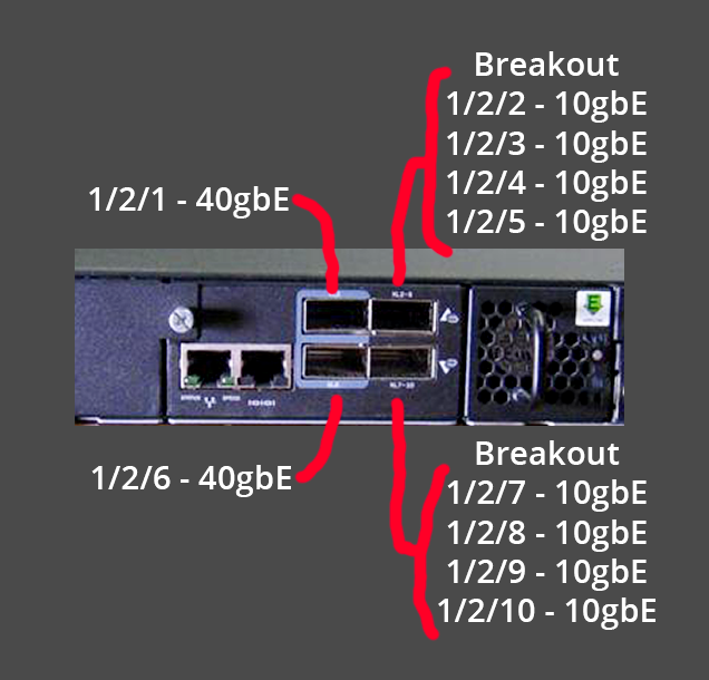
- The 40G ports on the back of the switch are numbered 1 thru 8. They exist in module 2. The 40G-only ports are 1/2/1 and 1/2/6 and are closest to the console port. NOTE that the 40G-only ports will not operate in breakout mode, nor will they operate at 10G. The breakout-only ports are 1/2/2 thru 1/2/5 for the top port, and 1/2/7 thru 1/2/10 for the bottom port. These breakout ports are closest to the fan. NOTE that the breakout ports will not operate at 40G, and will only work as four 10G links
Console Cable
This was JohnB's first time needing to use a console cable to set up a device, so this section serves to familiarize a newcomer with the process.
Many IT devices such as APC UPS battery backups, Cisco switches, and Ubiquiti gear have an RJ45 port labeled "Console" that can be used to configure or talk to the device. In some cases, configuration must occur with this method before more convenient configuration methods such as SSH or a Web UI are available. These RJ45 ports can have different wiring methods, so an APC RJ45 to DB9 cable is electrically different from a Cisco RJ45 to DB9 cable.
A normal serial adapter (say a Raspberry Pi or an ESP8266 or Arduino or ESP32) will only work with 3.3V or 5V logic, and will be incompatible with the 12V signals needed to talk to the networking devices. A specific adapter cable is needed. Because the RJ45 wiring can be different depending on the manufacturer, it's better to get a USB to DB9 cable than a USB to RJ45 cable. The Eaton/Tripp Lite Keyspan adapter is the OG, but cheaper options with the Prolific PL2303 chip work fine as well (USB-A option or the USB-C option JohnB got).
Once the cable is plugged into a computer, it should show up in USB Devices or Device Manager, but it may not be immediately ready to use. JohnB got hung up on a Macbook Pro M1 running macOS 14.3 where the device showed up in System Report but was not showing up as a serial connection. As per the instructions, ls -ltr /dev/*usb* was supposed to show the device, but there were no matches. There might have been an issue with kext Kernel Extensions and the installer provided on the websites (Prolific driver, Cable Matters driver(SKU 201060), they're the same). What ended up working was to install the driver via the App Store. After that, the device showed up as /dev/tty.PL2303G-USBtoUART110 and /dev/cu.PL2303G-USBtoUART110. What's the difference? TTY devices are for calling into UNIX systems, whereas CU (Call-Up) devices are for calling out from them (eg, modems), so /dev/cu.* is the correct device to use
Now the connection can be made. Connect the RJ45 to DB9 cable of choice (the blue Cisco cable works fine for the Brocade switch) and plug it in to the console port on the switch. Plug in the USB end. The screen Terminal command works and is installed by default, and the console session can be started with screen /dev/cu.PL2303G-USBtoUART110 9600 where 9600 is the baud rate in bits per second (9600 is pretty universal). Power cycle the switch and it should immediately start outputting content. For example:
ICX Boot Code Version 10.1.00 (grz10100)
Enter 'a' to stop at memory test
Enter 'b' to stop at boot monitor
BOOT INFO: load monitor from boot flash, cksum = 71f1
BOOT INFO: verify flash files.........
BOOT INFO: load image from primary copy...
platform type = 12
PCIE-1 LTSSM status: 22
PCIE Switch status: 0
..............................
Firmware integrity checksum passed
JohnB found that backspace did not work, and a mis-type would require pushing ENTER to finish the command or CTRL + C to clear the line.
An alternative to screen is minicom which is recommended by some people. Minicom can be installed on macOS with Homebrew, for example brew install minicom. JohnB has yet to set up minicom so a TODO is to finish this section with usage details on Minicom. Thishas some good information
TFTP Setup
To update the software of the Brocade switch, a TFTP server needs to be running on the same network as the switch. This ServeTheHome user set up a websitewith detailed instructions.
JohnB's abbreviated TFTP setup notes are:
- Install Linux Mint (Ubuntu base)
-
Download the firmware files and extract them in the home directory. In this case, the files are in
/home/test/brocade-12-19-2023/ - Modify the permissions download directory with
chmod --recursive 777 /home/test/brocade-12-19-2023/, otherwise Permission Denied errors might show up - Install TFTP server with
sudo apt install tftpd-hpa - Modify TFTP server settings with
nano /etc/default/tftpd-hpato match the following lines. This will remove the username, set the root directory to serve as the TFTP-Content directory from the earlier extract, serve TFTP on port 69, and print extra information in the logs
TFTP_USERNAME="nobody"
TFTP_DIRECTORY="/home/test/brocade-12-19-2023/TFTP-Content"
TFTP_ADDRESS="0.0.0.0:69"
TFTP_OPTIONS="--secure -vvvv"
- Restart the service with
systemctl restart tftpd-hpato apply the settings - (Optional) Monitor the TFTP server's activity with
tail -F /var/log/syslog. This will show connection attempts, errors, transferred files, and more - (Optional) Test the TFTP server functionality with another computer. Assuming the TFTP server's IP is 10.1.1.2, use another computer and follow these instructions
- Connect to the TFTP server with
tftp 10.1.1.2and it should connect, dropping into atftp >prompt - Try to get a file with
get ICX6610-FCX/grz10100.binand it should copy it to the current working directory - Exit the TFTP prompt with
quit
- Connect to the TFTP server with
Resources
-
ServeTheHome forum thread where johnb found out about these https://forums.servethehome.com/index.php?threads/brocade-icx-series-cheap-powerful-10gbe-40gbe-switching.21107/
-
Useful info on Console/Serial cables, Screen, Minicom https://pbxbook.com/other/mac-tty.html
-
USB-C to Serial/DB9/Console cable with Prolific PL2303 chip https://www.amazon.com/Cable-Matters-Serial-Adapter-USB-C/dp/B075GV6VL1 (SKU 201060). macOS App Store driver https://apps.apple.com/us/app/pl2303-serial/id1624835354?mt=12
-
Fohdeesha TFTP and Brocade firmware setup https://fohdeesha.com/docs/brocade-overview.html
-
Fohdeesha ICX6610 firmware updating and initial configuration https://fohdeesha.com/docs/fcx.html
-
Fohdeesha ICX6610 SSH setup, DNS, NTP, PoE, etc https://fohdeesha.com/docs/icx6xxx-adv.html
-
Fohdeesha ICX6610 10G license unlocking https://fohdeesha.com/docs/6610.html
-
Youtube version of the setup process https://www.youtube.com/watch?v=yutgXiGZ4Y8
-
Mesh IP Network Number allocation (strategy 3, split the network number into two parts so NN584 becomes 10.69.5.84) https://wiki.mesh.nycmesh.net/link/94
-
Mesh Omni config generator, which gives some information on CIDR, IP, etc https://configgen.nycmesh.net/?version=v4.9&device=Omnitik5AC&template=omni-poe-ether5.rsc.tmpl
-
Mesh Juniper vs Mikrotik configuration detail https://wiki.mesh.nycmesh.net/link/127
2024/03/12 Notes
-
show ip interfaceto get output about the virtual interfaces attached to VLANs
SSH@nycmesh-nn584-brocade-poe-switch#show ip interface
Interface           IP-Address      OK?  Method    Status             Protocol   VRF
Ve 1                10.69.5.84      YES  manual    up                 up         default-vrf
                    10.97.227.165
Ve 10               10.10.10.10     YES  manual    up                 up         default-vrf
- once entered into a VLAN, say with
vlan 11then runningno untagged ethernet 1/2/6would remove the interface from that VLAN. Theshow interfaces briefshould show the PVID to have changed to the VLAN ID if the ports were set to untagged - Then create a virtual interface to go with that VLAN, say
interface ve 11and then add an IP/network to it withip address 10.70.196.1/23 - Create a DHCP pool with
ip dhcp-server pool meshbridgewhich does not yet have an address space or network associated with it. Set the network withnetwork 10.96.146.0/26and then set the first section of the range as excluded withexcluded-address 10.96.146.1 10.96.146.10. Thenshow runshould show the configured DHCP server info:
ip dhcp-server pool meshbridge
 excluded-address 10.96.146.1 10.96.146.10
 lease 1 0 0
 network 10.96.146.0 255.255.255.192
!
- https://www.reddit.com/r/networking/comments/5ivjji/i_dont_understand_brocade_ves/ had some good descriptions of virtual interfaces (VEs)
vlan 100 name Example_VLAN
 untag ethernet 1 to 10
 router-interface ve100

interface ve 100
 ip address 192.168.100.1/24
You build the VLAN, associate it with some interfaces, then associate a VE with the VLAN. That creates the map between the VLAN, interfaces, and VE. Then you configure the VE. It's a virtual interface. Traditionally, you would have a router connected to a switch. The switch would connect hosts, then pass a single network segment (aka VLAN 1 in today's terms) or multiple VLANs to a stand-alone router, which would have the IP address configured on a physical interface. These virtual Ethernet (VE) or switch virtual interfaces (SVIs) are the logical equivalent of a physical router port. Think of it is as a virtual router inside the switch. VEs/SVIs will allow you more flexibility in terms of having multiple networks be trunked over a single interface. The biggest caveat is that the VE will not come up until the vlan is assigned to the interface. So if you create VLAN 10, and then assign VE 10 to that. Until you assign an interface to Vlan10, you will not be able to access the VE
- For tagging Bonds/LACP/LAGs made up of multiple interfaces, one resource https://community.ruckuswireless.com/t5/ICX-Switches/tagging-a-VLAN-on-lag-port/m-p/29492/highlight/true noted that the lag can be added to a VLAN directly using its ID. For example:
config t

vlan 3000

tag lag 1

write mem
-
Someone else notes though that if the ports were in a vlan prior to the creation of the lag, those vlan tags should already be present (ports converted to lag syntax)
-
The brocade documentation notes
device(config)# vlan 2 name IP-Subnet_10.1.2.0/24
device(config-vlan-2)# untag ethernet 1 to 4
device(config-vlan-2)# tag ethernet 5 to 8
device(config-vlan-2)# router-interface ve 1
device(config-vlan-2)# interface ve 8
device(config-vif-8)# ip address 10.1.2.1/24
The first three commands in this example create a Layer 3 protocol-based VLAN name "IP-Subnet_10.1.2.0/24" and add a range of untagged and tagged ports to the VLAN. The last two commands move the configuration to the interface configuration mode for the virtual interface and assign an IP address to the interface. The router-interface command creates virtual interface 8 as the routing interface for the VLAN.
- Quincy looked up the IP ranges and started calculating ranges on the fly for Olmsted, NN584. First is the mesh bridge IP built from the node number, which in this case was 10.69.5.84/16 (not sure why the /16 was chosen).
- Then comes the second IP on the mesh bridge VLAN, this one being 10.96.146.1/26 which is the 64 address DHCP range allocated for this node number. Quincy got this from picking the 584th /26 after 10.69.5.84
- Then we need a DHCP range to address all the 400+ ONUs in the apartments. This selection is done manually. A /23 is chosen for its 512 addresses because a /24 would only be 256 addresses. Quincy picked 10.70.196.0/23 for this range
- Then we need a DHCP range for management devices (out-of-band or OOB) such as APs, battery backups, switches, and other devices. A /26 (64 addresses) would do but can be more annoying to keep track of, so a /24 (256 addresses) can be used. Quincy picked the network range of 10.70.198.0/24 with the VLAN virtual interface address being 10.70.198.1
- Finally, a network range is needed for the transit to the data center. Quincy picked a /30 which has two usable addresses (outside broadcast and the base network address) so 10.70.251.72/30 was chosen, meaning 10.70.251.73 and 10.70.251.74 are the usable addresses.
vlan 1 name DEFAULT-VLAN by port
 router-interface ve 1
!
vlan 10 name meshbridge by port
 tagged ethe 1/3/1 to 1/3/2
 untagged ethe 1/1/47 to 1/1/48 ethe 1/3/3
 router-interface ve 10
!
vlan 11 name OLTs by port
 untagged ethe 1/2/2 to 1/2/5
 router-interface ve 11
!
vlan 12 name OOB by port
 tagged ethe 1/3/1 to 1/3/2
 untagged ethe 1/1/40
 router-interface ve 12
!
vlan 20 name Transit by port
 untagged ethe 1/2/1
 router-interface ve 20

 interface ve 1
 ip address 10.97.227.165 255.255.255.0
!
interface ve 10
 ip address 10.69.5.84 255.255.0.0
 ip address 10.96.146.1 255.255.255.192
!
interface ve 11
 ip address 10.70.196.1 255.255.254.0
!
interface ve 12
 ip address 10.70.198.1 255.255.255.0
!
interface ve 20
 ip address 10.70.251.73 255.255.255.252
-
show ip intcan show all the active IP addresses running on the switch
SSH@nycmesh-nn584-brocade-poe-switch#show ip interface
Interface           IP-Address      OK?  Method    Status             Protocol   VRF
Ve 1                10.69.5.84      YES  manual    up                 up         default-vrf
                    10.97.227.165
Ve 10               10.10.10.10     YES  manual    up                 up         default-vrf
-
show lagcan show the current status of a deployed LAG/LACP/802.3ad/bond. The setup is also included
lag roof dynamic
ports ethernet 1/3/1 ethernet 1/3/2
primary-port ethernet 1/3/1
deploy


show lag


Total number of LAGs:          1
Total number of deployed LAGs: 1
Total number of trunks created:1 (119 available)
LACP System Priority / ID:     1 / 748e.f8fe.b92a
LACP Long timeout:             120, default: 120
LACP Short timeout:            3, default: 3

=== LAG "roof" ID 1 (dynamic Deployed) ===
LAG Configuration:
   Ports:         e 1/3/1 to 1/3/2
   Port Count:    2
   Primary Port:  1/3/1
   Trunk Type:    hash-based
   LACP Key:      20001
Deployment: HW Trunk ID 1
Port       Link    State   Dupl Speed Trunk Tag Pvid Pri MAC             Name
1/3/1      Up      Forward Full 10G   1     No  1    0   748e.f8fe.b92a
1/3/2      Up      Forward Full 10G   1     No  1    0   748e.f8fe.b92a

Port       [Sys P] [Port P] [ Key ] [Act][Tio][Agg][Syn][Col][Dis][Def][Exp][Ope]
1/3/1           1        1   20001   Yes   L   Agg  Syn  Col  Dis  No   No   Ope
1/3/2           1        1   20001   Yes   L   Agg  Syn  Col  Dis  No   No   Ope


 Partner Info and PDU Statistics
Port          Partner         Partner     LACP      LACP
             System ID         Key     Rx Count  Tx Count
1/3/1    65535-48a9.8ae8.3388       15        4         4
1/3/2    65535-48a9.8ae8.3388       15        4         4
- Name interfaces for easy reference to what's plugged in:
enable
configure terminal
SSH@nycmesh-nn584-brocade-poe-switch(config-if-e10000-1/3/1)#interface ethernet 1/3/3
SSH@nycmesh-nn584-brocade-poe-switch(config-if-e10000-1/3/3)#port-name roof_fiber_3_rack_hex
SSH@nycmesh-nn584-brocade-poe-switch(config-if-e10000-1/3/3)#interface ethernet 1/3/1
SSH@nycmesh-nn584-brocade-poe-switch(config-if-e10000-1/3/1)#port-name roof_fiber_1_outside_netpower
SSH@nycmesh-nn584-brocade-poe-switch(config-if-e10000-1/3/1)#interface ethernet 1/1/47
SSH@nycmesh-nn584-brocade-poe-switch(config-if-e1000-1/1/47)#port-name ubiquiti_olt_mgmt
SSH@nycmesh-nn584-brocade-poe-switch(config-if-e1000-1/1/47)#interface ethernet 1/1/48
SSH@nycmesh-nn584-brocade-poe-switch(config-if-e1000-1/1/48)#port-name apc_ups_nmc_mgmt
SSH@nycmesh-nn584-brocade-poe-switch(config-if-e1000-1/1/48)#write mem
Write startup-config done.
- Set up DHCP
ip dhcp-server pool meshbridge
 dns-server 10.10.10.10
 domain-name nycmesh.net
 excluded-address 10.96.146.1 10.96.146.10
 lease 1 0 0
 network 10.96.146.0 255.255.255.192
!
!
ip dhcp-server pool olts
 dns-server 10.10.10.10
 domain-name nycmesh.net
 excluded-address 10.70.196.1 10.70.196.10
 lease 1 0 0
 network 10.70.196.0 255.255.254.0
!
!
ip dhcp-server pool oob
 excluded-address 10.70.198.1 10.70.198.10
 lease 1 0 0
 network 10.70.198.0 255.255.255.0
!
- Here are the addresses we ended up setting, and their subnets/network ranges
interface ve 1
 ip address 10.97.227.165 255.255.255.0
!
interface ve 10
 ip address 10.69.5.84 255.255.0.0
 ip address 10.96.146.1 255.255.255.192
!
interface ve 11
 ip address 10.70.196.1 255.255.254.0
!
interface ve 20
 ip address 10.70.251.73 255.255.255.252
!
- Show information about the SFP modules:
optical-monitor (to enable optic monitoring)
show media (to list all the different things installed in the different ports, shows the SFP module info)

Port 1/3/1:  Type : 10GE LR 10km (SFP +)
Port 1/3/2:  Type : 10GE LR 10km (SFP +)
Port 1/3/3:  Type : 1G M-GBXD(SFP)
Port 1/3/4:  Type : EMPTY

show optic 1/3/3 (should show information but doesn't)

show media validation (to show the detail on the optics)

Port       Supported Vendor               Type
----------------------------------------------------------------------
1/3/1      Yes       FS                    Type  : 10GE LR 10km (SFP +)
1/3/2      Yes       FS                    Type  : 10GE LR 10km (SFP +)
1/3/3      Yes       FS                    Type  : 1G M-GBXD(SFP)

show media ethernet 1/3/3 (shows more detail about the optic)

Port   1/3/3: Type  : 1G M-GBXD(SFP)
	     Vendor: FS               	Version:
	     Part# : SFP-GE-BX        	Serial#: G2330171249
2024/03/19 Final Config Notes
- Starting Point
vlan 10 name meshbridge by port
 tagged ethe 1/1/48
 untagged ethe 1/1/1 to 1/1/6
vlan 11 name OLTs by port
tagged ethe 1/1/48
 untagged ethe 1/1/7 to 1/1/12
vlan 12 name OOB by port
 untagged ethe 1/1/13 to 1/1/18
 tagged ethe 1/1/48
vlan 20 name Transit by port
untagged ethernet 1/1/19 to 1/1/24
tagged ethernet 1/1/48


router-interface ve 10
 ip address 10.96.146.1 255.255.255.192
!
router-interface ve 11
 ip address 10.70.196.1 255.255.254.0
!
router-interface ve 12
 ip address 10.70.198.1 255.255.255.0
!
router-interface ve 20
 ip address 10.70.251.73 255.255.255.252
-
show ip routecan show information about the different routes deployed to the virtual interfaces. It also shows the OSPF routes communicated by its neighbor routers, meaning it could end up showing thousands of routes
nycmesh-nn584-brocade-poe-switch#show ip route
Total number of IP routes: 7
Type Codes - B:BGP D:Connected O:OSPF R:RIP S:Static; Cost - Dist/Metric
BGP  Codes - i:iBGP e:eBGP
OSPF Codes - i:Inter Area 1:External Type 1 2:External Type 2
       Destination        Gateway         Port          Cost          Type Uptime
1       10.69.5.84/32      10.70.251.78    ve 30         110/1         O    34m20s
2       10.70.196.0/23     DIRECT          ve 11         0/0           D    46m36s
3       10.70.198.0/24     DIRECT          ve 12         0/0           D    44m52s
4       10.70.251.72/30    DIRECT          ve 20         0/0           D    43m3s
5       10.70.251.76/30    DIRECT          ve 30         0/0           D    39m3s
6       10.96.146.0/26     10.70.251.78    ve 30         110/21        O1   34m20s
7       192.168.88.0/24    10.70.251.78    ve 30         110/21        O1   34m20s
- https://www.hpe.com/psnow/resources/ebooks/a00113859en_us_v2/Configure_a_Brocade_Management_Switch.html this has some info on initial config, SSH, etc.
2024-05-01 Additional Notes
- Connect with SSH + some extra flags
ssh -oKexAlgorithms=+diffie-hellman-group1-sha1 -oHostKeyAlgorithms=+ssh-rsa root@10.70.196.1 - Trying to see if ONUs are getting DHCP leases from the Brocade?
show ip dhcp-server bindingshould do this. https://docs.ruckuswireless.com/fastiron/08.0.50/fastiron-08050-dhcpguide/GUID-DE4FAA51-B284-4A8B-B50E-94087A914BBE.html
SSH@nycmesh-nn584-brocade-poe-switch(config)#show ip dhcp-server binding
Bindings from all pools:
        IP Address    Client-ID/        Lease expiration Type
                      Hardware address

      10.70.196.21    7088.6b83.0d7a   000d:15h:14m:11s   Automatic
      10.70.196.22    d021.f910.6c60   000d:19h:53m:12s   Automatic
- See how many leases have been handed out with
show ip dhcp-server summary
SSH@nycmesh-nn584-brocade-poe-switch(config)#show ip dhcp-server summary

DHCP Server Summary:

                    Total number of active leases:  2
           Total number of deployed address-pools:  2
         Total number of undeployed address-pools:  0
                                    Server uptime:  01d:06h:18m:31s
- See the general DHCP server configuration with
show ip dhcp-server address-pools. Note that in the below printout, the OOB portion of the switch is disabled, so the CCR1009 is handing out DHCP, not the Brocade. The Brocade is only being used for the OLT/ONU IP addresses (aka the 400 boxes in everyone's apartment)
SSH@nycmesh-nn584-brocade-poe-switch(config)# show ip dhcp-server address-pools

Showing all address pool(s):


                    Pool Name:  olts
 Time elapsed since last save:  00d:00h:20m:51s
Total number of active leases:  0
           Address Pool State:  active
        IP Address Exclusions:  10.70.196.1 10.70.196.20
      Pool Configured Options:
          dhcp-default-router:  10.70.196.1
                   dns-server:  10.10.10.10
                  domain-name:  nycmesh.net
                        lease:  1 0 0
                      network:  10.70.196.0 255.255.254.0

                    Pool Name:  oob
 Time elapsed since last save:  00d:00h:20m:51s
Total number of active leases:  0
           Address Pool State:  active
        IP Address Exclusions:  10.70.198.1 10.70.198.20
      Pool Configured Options:
          dhcp-default-router:  10.70.198.1
                   dns-server:  10.10.10.10
                  domain-name:  nycmesh.net
                        lease:  1 0 0
                      network:  10.70.198.0 255.255.255.0
- Find the MAC address connected to any given port with
show mac-address ethernet 1/1/4
show mac-address ethernet 1/1/4
Total active entries from port 1/1/4 = 1
MAC-Address     Port                 Type          Index  VLAN
d83a.dda4.31cf  1/1/4                Dynamic       37340  12
- Flip a port off and on to renegotiate by selecting it and running
disableand thenenable.show interfaces eth 1/1/4can be used to verify the port's status
SSH@nycmesh-nn584-brocade-poe-switch>enable
SSH@nycmesh-nn584-brocade-poe-switch#configure terminal
SSH@nycmesh-nn584-brocade-poe-switch(config)#int eth 1/1/4
SSH@nycmesh-nn584-brocade-poe-switch(config-if-e1000-1/1/4)#disable
SSH@nycmesh-nn584-brocade-poe-switch(config-if-e1000-1/1/4)#enable