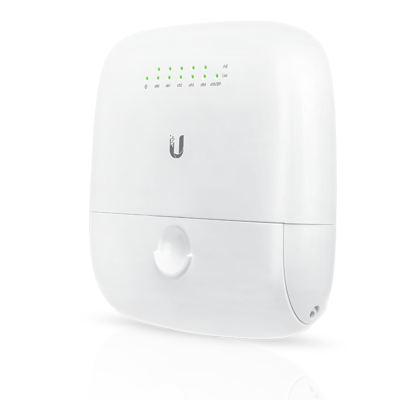
Ubiquiti EdgePoint R6
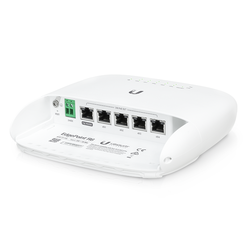
The EP-R6 is an outdoor rooftop switch/router with 6 ports (5 GigE, 1 SFP). It supports PoE, but only Ubiquiti's 24v Passive PoE style, not any of the fancier types.
It can be configured in switch mode (just a switch, with a management console) or routing mode (hub node setup, BGP, etc).
Device specs are available at store.ubnt.com.
Reset
To factory reset an EP-R6, press and hold the reset button, by the ethernet plugs, for about 10 seconds until the eth4 LED begins to flash, then release the button. The device will reboot and reset.
Or, reset it via the CLI by running the following commands:
sudo cp /opt/vyatta/etc/config.boot.default /config/config.boot
reboot
Connecting
The EP-R6 has a Web GUI and CLI.
The initial IP address out of the box is 192.168.1.1, the Web GUI is at https://192.168.1.1 Set you computer's local IP to something similar ( 192.168.1.5 ), and connect to switch on port eth0.
Although there is a Web GUI, using SSH can allow for a much more rapid workflow. If possible, use that.
Here is an example of SSHing to the EdgePoint when it is in factory default mode:
laptop$ ssh -o StrictHostKeyChecking=no ubnt@192.168.1.1
Welcome to EdgeOS
...

ubnt@192.168.1.1's password: ubnt
Linux ubnt 3.10.14-UBNT #1 SMP Wed Nov 11 14:42:04 PST 2015 mips
Welcome to EdgeOS
ubnt@ubnt:~$
From here you can apply commands such as the ones below.
Device idiosyncrasies
Hardware NAT
If using the device as a router in NAT mode ( not router on the mesh ), the default settings will yield a very slow connection.
Hardware NAT should be enabled, which was just possible as of firmware version v1.9.7.
This page at Ubnt discusses more: https://help.ubnt.com/hc/en-us/articles/115006567467-EdgeRouter-Hardware-Offloading-Explained
To enable hardware offload on this model, perform the following commands on the CLI:
configure
set system offload hwnat enable
commit
save
exit
Safely Upgrading Old Devices
As some of these devices can be nearly a decade old (datasheet released in October 2015), you may come across devices with varying versions of firmware. A problem can present itself when you upgrade these older devices to the v2 line of firmware from the v1 firmware without taking the steps to upgrade the bootloader first, which is a manual process that can result in a bricked device (not unrecoverable, but requires disassembly and a TTL serial adapter - best to avoid!).
If you come across such a device, the first thing to do is to upgrade the device to a safe firmware that is new enough to contain the new boot-image but old enough to support devices running the old firmware. v1.10.7 seems to work for this purpose, and its changelog references significant bootloader-related fixes that result in an easier experience.
Once you have downloaded the .tar file, you can use the GUI to upgrade the firmware by uploading the image as described in the documentation. However, to avoid frustration it is recommended to take the steps on checking for free space on the device before uploading the file as the file upload fails uncleanly when there is no space and you may not realize what is going on.
- ssh into the device (ubnt@192.168.1.1, for example)
df -h- check the output and confirm that the root / mount point has enough free space to accept the 70-80MB image you will upload
ubnt@ubnt:~$ df -h
Filesystem                Size      Used Available Use% Mounted on
ubi0_0                  214.9M    141.1M     69.1M  67% /root.dev
overlay                 214.9M    141.1M     69.1M  67% /
...
Uh-oh, looks like we have less than 70M free on the root partition, so uploading the file via the GUI will fail and cause problems. We can solve this by removing the backup firmware first.
show system image, and confirm that there are two images uploaded to the devicedelete system image, and confirm that you want to remove the backup imagedf -h, to confirm that the space has been freed
ubnt@ubnt:~$ show system image
The system currently has the following image(s) installed:

v2.0.9-hotfix.7.5622731.230615.0857 (running image) (default boot)
v1.10.7.5127989.181001.1227

ubnt@ubnt:~$ delete system image
The system currently has the following image(s) installed:

v2.0.9-hotfix.7.5622731.230615.0857 (running image) (default boot)
v1.10.7.5127989.181001.1227

You are about to delete image [v1.10.7.5127989.181001.1227]
Are you sure you want to delete ? (Yes/No) [Yes]: yes
Removing old image... Done
ubnt@ubnt:~$ df -h
Filesystem                Size      Used Available Use% Mounted on
ubi0_0                  214.9M     66.7M    143.5M  32% /root.dev
overlay                 214.9M     66.7M    143.5M  32% /
...
Now you can proceed to upload the firmware via the GUI. Once you reboot, it is time to upgrade the bootloader by SSHing into device again, and it may have prompted you to do this on login:
Linux ubnt 4.14.54-UBNT #1 SMP Thu Jun 15 09:00:10 UTC 2023 mips
Boot image can be upgraded to version [ e52_002_4c817 ].
Run "add system boot-image" to upgrade boot image.
Last login: Wed Dec 31 22:33:11 2014 from 192.168.1.100
ubnt@ubnt:~$
You can do as instructed and it is recommended to reboot the device before moving onto the next firmware:
ubnt@ubnt:~$ add system boot-image
Uboot version [e52_001_1e49c] is about to be replaced
Warning: Don't turn off the power or reboot during the upgrade!
Are you sure you want to replace old version? (Yes/No) [Yes]: yes
Preparing to upgrade...Done
Copying upgrade boot image...Done
Checking boot version: Current is e52_001_1e49c; new is e52_002_4c817 ...Done
Checking upgrade image...Done
Writing image...Boot image has been upgraded.
Reboot is needed in order to apply changes!
Done
Upgrade boot completed
ubnt@ubnt:~$ reboot now

Broadcast message from ubnt@ubnt (pts/0) (Wed Dec 31 22:41:05 2014):

The system is going down for reboot NOW!

Connection to 192.168.1.1 closed by remote host.
Once it comes back, you can now upgrade to a v2 firmware using the GUI without any risk of bricking. Be sure to check for free space and remove the old backup firmware again before uploading the new .tar file by following the above instructions again.
Common Configs
Switched Mode (Extend an OmniTik)
To convert the EP-R6 to switched mode, there's now a simple wizard in the GUI to help.
A common use case for the EP-R6 as a switch is to add more PoE-capable ports to an OmniTik router on the roof. In order to preserve isolation between these ports and on the OmniTik, we need to make the switch VLAN-Aware. The following instructions assume the OmniTik has been configured with the standard configuration and IP allocations.
1. Start the Wizard
In the web interface, navigate to the "Wizards" tab on the top right of the screen. On the left sidebar, click "Switch". Choose Static IP. You are probably connected directly to the switch right now, so you don't want to lose access to it while there's no DHCP server!
Log into the OmniTik you are planning on connecting the switch to; we are going to find an unused IP in its /26 subnet. On the left sidebar under IP->DHCP Server, click the "Leases" tab, and hit "Add New". Type in the address you are allocating, uncheck "Enabled", and type nycmesh-xxxx-epr6 in the "Comment" (where xxxx is the network number to which this will be attached).
Type this address into the switch with a /26 subnet with the OmniTik's /26 IP Address as the gateway. Use 10.10.10.10 as the DNS server.
2. Set the VLANs on the EP-R6
Under "VLAN Aware", check "Enabled". Depending on which port will be connected to the OmniTik (the "trunk" port), you will set the VLANs using a combination of the OmniTik's and the EP-R6's port numbers.
Example: EP-R6 is plugged into Port 3 on the OmniTik, and we want to isolate Ports 1-5 on the EP-R6.
eth0: vid 301,302,303,304,305
eth1: pvid 301
eth2: pvid 303
eth3: pvid 303
eth4: pvid 304
eth5: pvid 305
In layman's terms, The PVID tags the port and VID tells where to send the tagged traffic out. The first digit will be the port number of the OmniTik, and the last digit will be the port number of the EP-R6. After setting up your credentials you can hit apply and reboot the router.
3. Add the VLANs to the OmniTik
Because eth0 did not have a PVID set, you should be able to access the switch using its new IP address without additional hardware. However, we need to configure the OmniTik to receive the tagged traffic and add them to the mesh bridge.
Name: ether1.301
VLAN ID: 301
Interface: ether3
Hit OK to save. Once you do this for each port on the EP-R6, you can navigate to the left sidebar and go to Bridge. Under the "Ports" tab, click "Add New" for each VLAN you are configuring. Select the Interface you just created (ether1.301) and the Bridge mesh. Hit OK, and do this for each VLAN interface.
4. Test it!
The easiest way to test your configuration is by connecting a DHCP client (like a router) to the port and testing traffic flow. Plug it into any of the configured ports of the EP-R6, where you will see the port turn purple, orange, or green on the top of the EP-R6's GUI (purple:10Mbps, orange:100Mbps, green:1G).
Routed Mode ( NYCMesh Hub Node - BGP )
You will need to know the following to be able to continue: BGP ASN - Autonomous System Number within the network Gateway Node Y/N - Are we going to be a gateway exit node Peers ASN and IP - What are our Peer ASN and IP that we will connect with Local Subnet - What local network will we have? One? Many?
Configuration: The following sections below may be used in-part or in-whole depending on the need:
- Route Filters / Prefix list - Allows or denies certain ranges from the network. Good for ensuring functionality
- The current filter set for NYCMesh can be found at Filter
Example Parameters: ASN: 65012 Gateway: N Peer ASN: 65010 Peer IP: 10.180.14.1 Local Subnet: 10.70.50.0/24
configure

## Filters ##
set policy prefix-list nycmeshprefixes rule 10 prefix 10.0.0.0/8
set policy prefix-list nycmeshprefixes rule 10 ge 22
set policy prefix-list nycmeshprefixes rule 10 le 32
set policy prefix-list nycmeshprefixes rule 10 action permit

set policy prefix-list nycmeshprefixes rule 20 prefix 172.16.0.0/12
set policy prefix-list nycmeshprefixes rule 20 ge 24
set policy prefix-list nycmeshprefixes rule 20 le 32
set policy prefix-list nycmeshprefixes rule 20 action permit

set policy prefix-list defaultroute rule 10 prefix 0.0.0.0/0
set policy prefix-list defaultroute rule 10 action permit

set policy route-map nycmeshroutes rule 10 action permit
set policy route-map nycmeshroutes rule 10 match ip address prefix-list nycmeshprefixes

# BGP Config
set protocols bgp 65012
set protocols bgp 65012 neighbor 10.180.14.1 remote-as 65010
set protocols bgp 65012 neighbor 10.180.14.1 soft-reconfiguration inbound
set protocols bgp 65012 neighbor 10.180.14.1 nexthop-self
set protocols bgp 65012 neighbor 10.180.14.1 route-map import nycmeshroutes
set protocols bgp 65012 neighbor 10.180.14.1 route-map export nycmeshroutes

# BGP Network Config
set protocols bgp 65012 network 10.70.50.0/24
set protocols static route 10.70.50.0/24 blackhole

# Save and Reset BGP
commit
save
clear ip bgp all