5 - Networking
Design of the mesh network and explanations of core concepts
- Overview
- 10-69-Net-Network
- BGP
- Birdc
- Networking 101 Training Classes
- DNS
- Hubs
- Network Number
- IP Mapping Method
- Mesh Design Proposal
- Network Time Protocol (NTP)
- Peering
- Supernode-Architecture
- Virtual Private Network (VPN)
- OSPF
- NYC Mesh OSPF Routing Methodology
- Rules and Standards
- OSPF Configuration Guide
- Juniper Point-to-Point Guide
- 10 Gigabit
- Brocade Router CLI Notes
- Proxmox Cisco VLAN LACP SN3 Config
- Juniper DHCP Pool, LAG/LACP/AE/Bond, VLAN
Overview
NYC Mesh is a mesh network.
To understand a bit more about our Mesh network design concepts, please see Mesh Design
For more information on our networking concepts at a high level, please see:
We use the following routing protocols:
- BGP: Hub-to-Hub, some Rooftops, and to the Internet
- OSPF: Hubs to Rooftops, Rooftops to Rooftops, and in some VPNs
- BMX6: Older Openwrt Nodes (c. 2015), (Write-up pending)
You can connect to the network through:
- A wireless connection to an existing hub or node. See Nodes or the Map to locate one near you.
- VPN to the Mesh. See VPN
10-69-Net-Network
The 10-69 network is used to connect nodes on NYC Mesh. Every mesh router at every node on the mesh gets an IP address from 10.69.0.0/16. Each router's IP address can be computed from the router's node number. The 10-69 network supports up to two routers per node.
The 10-69 network allows for routers at nodes to auto-discover each other using OSPF with minimal configuration. This makes it possible for anyone to join the mesh with almost no intervention from other mesh members. All you need to do is request a node number. No IP addresses, subnets or VLANs have to be statically allocated, configuration can be auto-generated from your node number, and nobody has to log in to any routers at neighboring nodes to update their configuration. As long as you have line of sight to another node and configure your router to use OSPF on the 10-69 network, you can join the mesh.
Each mesh router bridges its wired and wireless interfaces together into a single interface. The 10-69 network is link-local to this bridge. The bridge's IP address is the router's 10-69 address, and every router sees 10.69.0.0/16 as directly connected in its routing table. Because the 10-69 network is link-local, you will never see 10.69.0.0/16 in the OSPF routing table. Instead, you will see a /32 (a route to a single host) for every router that's online.
All routers connected to the bridge are isolated from each other at layer 2. They can only talk to the router hosting the bridge. This is equivalent to a port-isolated switch with the host router on the uplink port. Without port isolation, the mesh would become a huge layer 2 broadcast domain: every router's bridge would be directly connected to every other router's bridge.
Port isolation also makes sure that the topology of the layer 2 network mirrors the physical layer's topology. A bridge without port isolation is a broadcast domain, but the mesh is primarily made up of point-to-point and point-to-multipoint radio links. If routers A and B connect wirelessly to router C's bridge, we want OSPF adjacencies for A-C and B-C, but not A-B. This is because routers A and B are not actually neighbors – all traffic between A and B has to flow through C.
All OSPF interfaces that use the 10-69 network are configured in point-to-multipoint mode. Like broadcast interfaces, PtMP interfaces can automatically discover their neighbors, so OSPF neighbors don't have to be set statically in the router's configuration. Unlike broadcast interfaces, RFC 2328 does not specify how OSPF should perform auto-discovery on PtMP interfaces. The mesh assumes that auto-discovery will be performed using the AllSPFRouters multicast IP address (224.0.0.5), but not all OSPF implementations support this. For PtMP interfaces, OSPF advertises a /32 to its address on that interface.
The ability to easily compute IP address from node number is also useful for troubleshooting: if you need to see if a node is reachable, convert its node number into its first router's 10-69 address and ping it.
In addition to the 10-69 network, a /26 for users of your node can be computed from your node number. The standard OmniTik config will hand these addresses out using DHCP. These addresses are computed linearly starting at 10.96.0.0/26 (followed by 10.96.0.64/26, 10.96.0.128/26, etc.).
Generating an IP address
The first router at each node can auto-generate its own 10-69 IP address using the following method:
The router's address will take the form of 10.69.X.Y. Take the node number and split it after the second digit. For example, node number 12345 becomes 123 and 45. The digits on the left, in this case 123, are bound to X, and the digits on the right are bound to Y, giving us 10.69.123.45.
Y can be between one and two digits, so it can't be greater than 99. X can in theory be any number of digits, but each number in an IPv4 address can only range from 0 to 255, so X can't be greater than 255. This means that the highest node number possible in this addressing scheme is 25,599.
For example:
| Node Number | X | Y | 10-69-net Address |
|---|---|---|---|
| 5 | 0 | 5 | 10.69.0.5 |
| 50 | 0 | 50 | 10.69.0.50 |
| 500 | 5 | 00 | 10.69.5.0 |
| 5000 | 50 | 00 | 10.69.50.0 |
| 50000 | X | Y | Not Possible |
| 25599 | 255 | 99 | 10.69.255.99 |
Adding a second router
Most of the time, one router per node is enough, but sometimes it's useful to add a second router.
To generate an address for a second router, just add 100 to Y. Going back to the previous example, the address of the second router at node 12345 would be 10.69.123.145.
For example:
| Node Number | X | Y | First router | Second Router |
|---|---|---|---|---|
| 5 | 0 | 5 | 10.69.0.5 | 10.69.0.105 |
| 50 | 0 | 50 | 10.69.0.50 | 10.69.0.150 |
| 500 | 5 | 00 | 10.69.5.0 | 10.69.5.100 |
| 5000 | 50 | 00 | 10.69.50.0 | 10.69.50.100 |
| 50000 | X | Y | Not Possible | Not Possible |
| 25599 | 255 | 99 | 10.69.255.99 | 10.69.255.199 |
BGP
The Border Gateway Protocol (BGP) is an inter-Autonomous System routing protocol.
NYC Mesh no longer uses BGP within the mesh between neighbors / members. Use of BGP within the mesh was too static for the changing network, lacked some "automatic" properties, and made it difficult to train new people.
Use outside NYC Mesh
BGP is a popular dynamic routing protocol as it is relatively simple to configure, scales well and enjoys support across multiple hardware and software vendors. The internet uses BGP to interconnect all the thousands of companies, ISPs, and Exchanges that make up the internet.
Use within NYC Mesh
NYC Mesh uses BGP to connect to the internet at Supernodes. In fact .. it is a requirement of a Supernode.
With BGP, we are able to connect our "Autonomous System" ( our organization's ID ) with other organizations, such as ISPs, and participate in the internet. By doing this, we carry our organization's IP addresses along with us and create many redundant connections to the internet.
Supernodes require BGP to connect to the internet because NYC Mesh has dedicated IP Addresses for use by our organization. In order to maintain proper functionality with the internet, we need to ensure we maintain a BGP connection at critical internet connection points, or, Supernodes.
Old Instructions
It is still possible to connect a BGP-only speaking device to the mesh, please coordinate with the larger group to do so, as it requires some planning.
Expand to see some older BGP information that is kept for informational purposes and the eventuality that BGP is needed for some devices
Expand to view details...
Communities
BGP communities can be used to classify routes that are imported or exported by an AS. Some definitions generally agreed upon by BGP speakers within the mesh are listed below. They are primarily used for interpreting the "quality" of various routes to the internet.
| Community | Meaning | Suggested interpretation |
|---|---|---|
| 65000:1001 | Internet connected by NYC Mesh | Set local preference to 130 |
| 65000:1002 | Internet connected by a fast, neutral 3rd party | Set local preference to 110 |
| 65000:1003 | Internet connected by a fast, non-neutral 3rd party | Set local preference to 100 |
| 65000:1004 | Internet connected by a slow, non-neutral 3rd party | Set local preference to 90 |
| 65000:1005 | Internet connected by a slow, NATed or possibly compromised 3rd party | Set local preference to 80 |
Prefix lists
IPv4 and IPv6 prefix lists that BGP speakers within the mesh commonly filter on (for import and export) are listed below:
IPv4
| Prefix (Bird notation) | Action |
|---|---|
| 199.167.59.0/24{24,32} | Allow |
| 10.0.0.0/8{22,32} | Allow |
| 0.0.0.0/0 | Allow |
| All others | Deny |
IPv6
| Prefix (Bird notation) | Action |
|---|---|
| 2620:12d:400d::/48{48,64} | Allow |
| fdff:1508:6410::/48{64,128} | Allow |
| ::/0 | Allow |
| All others | Deny |
How to get an ASN or IP allocation
Currently the mesh uses a spreadsheet to keep track of allocated resources. The process will be automated soon, but in the mean time please contact an existing member via Slack or email to have them help you acquire an ASN and IPv4 and/or IPv6 resources.
Examples
Some configuration examples for BGP implementations known to be in use within NYC Mesh today are listed below in no particular order.
Bird
Bird is an open source routing daemon with support for a number of different routing protocols including BGP.
**Expand Bird Example**
``` log stderr all;
router id 10.70.x.1;
function is_mesh_prefix_v4 () { return net ~ [ 199.167.59.0/24{24,32}, 10.0.0.0/8{22,32}, 0.0.0.0/0 ]; }
function is_mesh_prefix_v6 { return net ~ [ 2620:12d:400d::/48{48,64}, fdff:1508:6410::/48{64,128}, ::/0 ]; }
function set_local_pref () { if (65000,1001) ~ bgp_community then bgp_local_pref = 130; if (65000,1002) ~ bgp_community then bgp_local_pref = 110; if (65000,1003) ~ bgp_community then bgp_local_pref = 100; if (65000,1004) ~ bgp_community then bgp_local_pref = 90; if (65000,1005) ~ bgp_community then bgp_local_pref = 80; }
filter is_not_deviceroute { if source = RTS_DEVICE then reject; accept; }
filter mesh_import_v4 { if ! is_mesh_prefix_v4() then reject; set_local_pref(); accept; }
filter mesh_export_v4 { if ! is_mesh_prefix_v4() then reject; if ifname = "eth0" then bgp_community.add((65000,1005)); accept; }
filter mesh_import_v6 { if ! is_mesh_prefix_v6() then reject; set_local_pref(); accept; }
filter mesh_export_v6 { if ! is_mesh_prefix_v6() then reject; if ifname = "eth0" then bgp_community.add((65000,1005)); accept; }
protocol device { scan time 10; }
protocol direct { ipv4; interface "br0" "eth0"; }
protocol kernel { scan time 10; ipv4 { export filter is_not_deviceroute; }; }
protocol kernel { scan time 10; ipv6 { export filter is_not_deviceroute; }; }
template bgp meshpeer { local 10.70.x.1 as 65xxx; hold time 15; keepalive time 5; ipv4 { next hop self; import filter mesh_import_v4; export filter mesh_export_v4; }; ipv6 { next hop self; import filter mesh_import_v6; export filter mesh_export_v6; }; }
protocol bgp n1234 from meshpeer { neighbor 10.70.x.y as 65yyy; }
</details>
### [UBNT/EdgeOS](https://www.ubnt.com/products/#edgemax)
UBNT's EdgeOS was forked from Vyatta, which in turn borrows from [Quagga](https://www.nongnu.org/quagga/).
<details>
<summary>**Expand for UBNT/EdgeOS Example**</summary>
protocols { bgp 65xxx { neighbor 10.70.x.y { description n1234 nexthop-self remote-as 65yyy route-map { export nycmeshexport import nycmeshimport } soft-reconfiguration { inbound } } network 10.70.x.0/24 { } network 199.167.59.x/32 { } parameters { router-id 10.70.x.1 } timers { holdtime 15 keepalive 5 } redistribute { static { route-map nycmeshexportIspDefault } } } static { route 10.70.x.0/24 { blackhole { } } } } policy { community-list 101 { rule 10 { action permit regex 65000:1001 } } community-list 102 { rule 10 { action permit regex 65000:1002 } } community-list 103 { rule 10 { action permit regex 65000:1003 } } community-list 104 { rule 10 { action permit regex 65000:1004 } } community-list 105 { rule 10 { action permit regex 65000:1005 } } prefix-list nycmeshprefixes { rule 10 { action permit ge 22 le 32 prefix 10.0.0.0/8 } rule 20 { action permit ge 24 le 32 prefix 199.167.56.0/22 } rule 30 { action permit prefix 0.0.0.0/0 } } route-map nycmeshexport { rule 10 { action permit match { ip { address { prefix-list nycmeshprefixes } } } } rule 20 { action deny } } route-map nycmeshexportIspDefault { rule 10 { action permit match { interface eth0 } set { community "65000:1005 additive" } } rule 20 { action deny } } route-map nycmeshimport { rule 10 { action permit match { community { community-list 101 } } set { local-preference 130 } } rule 20 { action permit match { community { community-list 102 } } set { local-preference 110 } } rule 30 { action permit match { community { community-list 103 } } set { local-preference 100 } } rule 40 { action permit match { community { community-list 104 } } set { local-preference 90 } } rule 50 { action permit match { community { community-list 105 } } set { local-preference 80 } } rule 60 { action permit match { ip { address { prefix-list nycmeshprefixes } } } } rule 70 { action deny } } }
</details>
### [Mikrotik/RouterOS](https://wiki.mikrotik.com/wiki/Manual:TOC)
Mikrotik's RouterOS has its own closed source BGP implementation.
**TODO**
### [OpenBGPD](http://www.openbgpd.org/)
An example of a working configuration, abeit without BGP community rules, is available [here](https://github.com/bongozone/kibble/blob/master/src/etc/bgpd.conf).
<details>
Birdc
WireGuard is generally described on another page, here: VPN - Wireguard. This page is about what is needed to configure WireGuard for routing over the VPN; especially with a focus on OSPF.
A Note on Cryptokey Routing
It's worth a section to touch on the cryptokey routing feature of WireGuard and how it works with the mesh.
All WireGuard nodes list their peers in a configuration file. Among the peer configuration is a public key and a list of acceptable IP ranges for the peer. Once the tunnel is brought up, packets from inside the tunnel must match the IPs in the list. Packets are routed to the peer using the IP range list and encrypted for the destination peer with its specific public key. Given this, no two peers may have overlapping IP ranges. Therefore, routing through two different peers to another peer downstream, or the internet, on a single wireguard connection cannot be accomplished using WireGuard in this manner.
However, the cryptokey routing is per-interface. It's possible for an interface to allow "all IPs" ( 0.0.0.0/0 ) to/from a peer. All IPs and dynamic routing can be accomplished over a fully open WireGuard interface, but only with one other peer, and one new interface for each peer pair. Therefore for routed WireGuard connections a special configuration is required on both ends to make this possible.
Process
Each side of a routed WireGuard VPN link will need the following:
- A dedicated linux server to be the VPN router.
- A new WireGuard interface for the other side of the VPN.
- A routing daemon, probably BIRD, which can perform OSPF in PtP mode.
Dedicate Linux Server
The server on each side of the VPN will need to be configured appropriately. When handling the VPN, the server will have "two internets", and possibly other traffic direction. As such, it's important to configure the system correctly so that it does not "leak" traffic from the mesh onto the internet, vice versa, nor from any other network the same server handles. It is best to use a dedicated box, which will still need some custom "rules" to make it happen.
There are a few approaches to handle the traffic separation:
1) Multiple Routing Tables and firewalling
Linux has the ability to handle multiple routing tables. They are easy to define through a single file in the /etc/ path.
The BIRD routing daemon can also be configured to manage routes in the non-standard routing tables, so these two pieces easily work together.
One challenge with multiple routing tables is that a single device (WireGuard endpoint or Ethernet card) cannot be "tied" to a routing table. Instead, a rule (in addition to the firewall) is needed, to select the the routing table used for making a decision. These rules are easy to create but can be somewhat challenging to get right, and there is no good universal way to manage them.
Set up a new routing table for the mesh:
Edit /etc/iproute2/rt_tables and add a second table for the mesh:
$ vi /etc/iproute2/rt_tables
1 admin
2 nycmesh
3 public
Modify network file to add ip rules
Later in this write-up will describe how to add WireGuard interfaces and create their configuration in (if using Debian/Ubuntu) /etc/network/interfaces.d/*. If using the multiple routing tables method, additional lines will need to be added. They will be added in the example below, but show specificially here:
auto wg111
iface wg111 inet static
address 10.70.xx.1/31
pre-up ip link add $IFACE type wireguard
pre-up wg setconf $IFACE /etc/wireguard/$IFACE.conf
pre-up ip link set up dev $IFACE
pre-up ip route add 10.70.xx.1/31 dev $IFACE table nycmesh
pre-up ip rule add iif $IFACE pref 1031 table nycmesh
pre-up ip rule add from 10.70.xx.0 table nycmesh
post-down ip link del $IFACE
post-down ip rule del iif $IFACE table nycmesh
post-down ip rule del from 10.70.xx.0 table nycmesh
post-down ip link del $IFACE
Note the order of the pre-up and post-down rules, as it is critical. Some systems may vary in terms of the rules, depending on your distribution. Report back and help us update the document if something is off.
Note also the table nycmesh which is referenced by name. The name needs to match the rt_tables name.
Local Interfaces, to mesh-routers at the same site, will also need ip rules. For example:
# Mesh internal
allow-hotplug <Local Interface>
iface <Local Interface> inet static
address 10.69.XX.YY/16
post-up ip route add 10.69.0.0/16 dev $IFACE table nycmesh
post-up ip rule add iif $IFACE pref 1021 table nycmesh
post-up ip rule add from 10.69.XX.YY table nycmesh
post-down ip route del 10.69.0.0/16 dev $IFACE table nycmesh
post-down ip rule del iif $IFACE table nycmesh
post-down ip rule del from 10.69.XX.YY table nycmesh
2) Linux Namespaces / Containers.
Alternately, a newer Linux feature, namespaces, which is what containers are based on, can be used to provide segregation. Although containers and namespaces are intertwined, containers have a highly-simplified version of the general network namespace concept. As such, containers are not directly suitable for use as routing namespaces without much extra work. Therefore, the more challenging raw namespaces much be used.
This way has not yet been explored, it is more theoretical, so follow the first approach for now
WireGuard interface for each side
Each side's dedicated Linux server will need a new WireGuard interface for the connection. This is because each side needs to use 0.0.0.0/0 as the AllowedIPs so that any mesh address can be routed over the connection.
The connection will also need a pair of unique private IP addresses to route the internal traffic. At this time, the addresses should be taken from the NYC Mesh IP Ranges spreadsheet to ensure they are unique. Please ask Zach for an address pair.
Below are WireGuard configuration files which can be used as a basis for setting up a connect. (Be sure to replace the keys and addresses with the proper inputs).
Note the suggested device names -- It is recommended to name the interface as wgX where X is the destination node number the connection. This makes troubleshooting and configuration much easier..
Side 1 (Node 111):
# This is Node 111 Interface wg222
[Interface]
PrivateKey = ThisIsThePrivateKeyOnSide1
ListenPort = 51825
# Node 222
[Peer]
PublicKey = ThisIsThePublicKeyFromSide2
AllowedIPs = 0.0.0.0/0
Side 2 (Node 222):
# This is Node 222 Interface wg111
[Interface]
PrivateKey = ThisIsThePrivateKeyOnSide2
ListenPort = 51825
# Node 111
[Peer]
PublicKey = ThisIsThePublicKeyFromSide1
AllowedIPs = 0.0.0.0/0
Next, setup the VPN interfaces on each side to auto-start as part of the system. The below example will be for Debian/Ubuntu, but other Linux distribution are similar.
Side 1 (Node 111):
- Edit the file
/etc/network/interfaces.d/wg222.conf. Page the content as follows:
auto wg222
iface wg222 inet static
address 10.70.xx.0/31
pre-up ip link add $IFACE type wireguard
pre-up wg setconf $IFACE /etc/wireguard/$IFACE.conf
pre-up ip link set up dev $IFACE
pre-up ip route add 10.70.xx.1/31 dev $IFACE table nycmesh
pre-up ip rule add iif $IFACE pref 1031 table nycmesh
pre-up ip rule add from 10.70.xx.0 table nycmesh
post-down ip link del $IFACE
post-down ip rule del iif $IFACE table nycmesh
post-down ip rule del from 10.70.xx.0 table nycmesh
post-down ip link del $IFACE
Side 2 (Node 222):
- Edit the file
/etc/network/interfaces.d/wg111.conf. Page the content as follows:
auto wg111
iface wg111 inet static
address 10.70.xx.1/31
pre-up ip link add $IFACE type wireguard
pre-up wg setconf $IFACE /etc/wireguard/$IFACE.conf
pre-up ip link set up dev $IFACE
pre-up ip route add 10.70.xx.1/31 dev $IFACE table nycmesh
pre-up ip rule add iif $IFACE pref 1031 table nycmesh
pre-up ip rule add from 10.70.xx.0 table nycmesh
post-down ip link del $IFACE
post-down ip rule del iif $IFACE table nycmesh
post-down ip rule del from 10.70.xx.0 table nycmesh
post-down ip link del $IFACE
Bring Up the interface on each side like so:
#Side1# ifup wg222
#Side2# ifup wg111
To verify the tunnel is working, a ping from one side's address to the other side will yield a response. For Example:
#Side1# ping -c 2 10.70.89.1
PING 10.70.xx.1 (10.70.xx.1) 56(84) bytes of data.
64 bytes from 10.70.xx.1: icmp_seq=1 ttl=64 time=5.28 ms
64 bytes from 10.70.xx.1: icmp_seq=2 ttl=64 time=5.67 ms
--- 10.70.xx.1 ping statistics ---
2 packets transmitted, 2 received, 0% packet loss, time 1001ms
rtt min/avg/max/mdev = 5.280/5.479/5.678/0.199 ms
This indicates the tunnel is setup successfully.
Routing Daemon - Bird - OSPF
The routing daemon ( BIRD is recommended ) needs to be configured to properly convey the routes to/from the network.
Remember, it is important to not leak routes in or out of the network, especially if the VPN node it to be a transit node connecting far sides of the mesh.
Additionally, BIRD's OSPF implementation is a bit finicky -- For example, it does not fully support PTMP mode, unless it communicates with other BIRD instances.
Here is a recommended BIRD configuration for a VPN connection. Key lines will be discussed in-line in the comments.
# The router id should be the Node's 10-69-net IP.
# If the node number is 1234:
# If this is the first router, the IP is 10.69.12.34
# If this is the second router, the IP is 10.69.12.134 ( more likely )
# If this is the third router, the IP is 10.69.12.234 ( rare case; Last octet needs to be <255 )
# Important: Use this same number in your local mesh interface above!
router id <Our 10-69-net IP>;
protocol device {
scan time 10;
}
# Add Local interfaces here which will connect to other local routers, such as an Omni
protocol direct {
interface "<Local Interface>";
interface "wg*";
interface "dummy*";
}
protocol kernel {
# Only add this line below if using the multiple routing table method.
# Note this is referenced by number, use the correct number table from rt_tables file
kernel table 2;
scan time 10;
persist;
learn;
metric 64;
import none;
export filter {
if source = RTS_STATIC then reject;
accept;
};
}
protocol ospf {
import all;
export none;
area 0 {
# Add this interface clause for each local interface connecting to local routers
interface "<Local Interface>" {
# Cost of 1 is safe for this because it's just a local jumper to another router which has cost
cost 1;
# Use PtP is going to a Mikrotik Router. BIRD and Mikrotik dont speak the same PTMP
# Use PtMP if going to other BIRD instances
# Use Broadcast for special scenarios that make sense, such as at a supernode.
type ptp;
# Add Neighbors via IPs on that interface.
neighbors {
<Local Neighbor>;
};
};
# Make sure to use the "wgXXXX" interface for the remove node.
# Add one of these clauses for each wireguard connection
interface "wg<Other Node Number>" {
# Cost 15 is for a Really Good WireGuard connection. Cost of 40 is more typical for a VPN
cost 15;
# PTMP for other BIRD instances. If WireGuard it's gonna be linux so BIRD
type ptmp;
neighbors {
<Other WireGuard Node>;
};
};
};
}
Testing the configuration
Once everything is running, the WireGuard tunnel is operating, and BIRD is started, check to see if everything is connecting properly. It may be a good idea to not initially connect other mesh routers to the VPN router until after you verify it is communicating properly and not leaking routes.
Check BIRD functionality.
Start BIRD and check the OSPF protocol, see below:
# birdc
bird> show protocol
name proto table state since info
device1 Device master up 2020-03-14
direct1 Direct master up 2020-03-14
static1 Static master up 2020-03-14
kernel1 Kernel master up 2020-03-14
ospf1 OSPF master up 2020-03-14 Running
bird> show protocol all ospf1
name proto table state since info
ospf1 OSPF master up 2020-03-14 Running
Preference: 150
Input filter: ACCEPT
Output filter: REJECT
Routes: 464 imported, 0 exported, 461 preferred
Route change stats: received rejected filtered ignored accepted
Import updates: 64065 1 0 0 64064
Import withdraws: 16846 0 --- 2 16845
Export updates: 64067 64059 8 --- 0
Export withdraws: 16845 --- --- --- 0
bird> show route export ospf1
bird>
Above, we see show protocol lists ospf1 as Running. This means is has successfully connected to other nodes and is functioning properly. It may also say alone which could indicate a problem, or, could mean it has not yet connected ( it maybe take up to one minute ).
Next we see that inspecting the ospf protocol more, we have received 464 routes, and are exporting 0 routes This is the important part. In thie case exporting means we are adding some routes to the mesh. We may want to, for special cases, at this point, but if the VPN router is pass-through, then it should say 0 as a best practice.
Lastly, if we are exporting routes, we can check them with show route export ospf1. In this case we aren't so there's no problem. If we do, we can fix the problem with this knowledge.
There are many other commands within BIRD to help debug, check them out.
Networking 101 Training Classes
We have presented a few classes on network concepts and training. Here is a list of slides and videos we have made for reference.
-
Networking 101 version 1, by Zach Giles, Early 2017 Slides
-
Networking 101 version 2, by Zach Giles, December 2018 Slides, Video
DNS
DNS Infrastructure
NYCMesh maintains an internal DNS with the "fake" top-level domain (TLD) of .mesh ( dot mesh ).
Through this, services can be hosted, internal sites, etc.
Use 10.10.10.10 for your DNS server.
DNS configuration
The DNS is hosted using standard DNS zones which are made available through the Knot Resolver and Knot DNS Server.
The zone and scripts are made available via git. Once the master branch is updated, the DNS servers will periodically update and refresh their configuration.
Git Repo: github.com/nycmeshnet/nycmesh-dns
Git Repo: NYCMesh in-mesh git ( does not exist yet )
Anycast DNS and IPs
Anycast
The DNS system is available through a "trick" called Anycast. Anycast is the number one way DNS is provided on the main public internet. With anycast, many DNS servers all present the same virtual IP. They announce this IP in the routing table ( mesh routing table, BGP or other protocol ). With this, the clients believe they all have a very short route to the same network, but in fact it is a copy of the same service running many times with the same configuration. Any of the services may answer the request equally well. Reply packets are sent via the normal means.
IPs
10.10.10.10 - Resolving DNS endpoint for the mesh ( Use this one )
10.10.10.11 - Authoritative endpoint for dot-mesh TLD.
199.167.59.10 - Public DNS Resolver for anyone in the world. No Logs, No filtering.
The reason for two endpoints rather than one is to enable resolving the dot-mesh TLD separately. In-fact, the caching resolver forwards to the dot-mesh TLD server for dot-mesh addresses.
This also allows more than one node to host a resolver, or, a dot-mesh DNS server, or both.
Top Level Domains
.mesh- Internal dot-mesh domain for NYC Mesh..mesh.nycmesh.net- Public version of the same domain. Equivilent of.mesh. Available on the entire internet
Running a DNS Server
This is a Work in progress
Today there is a DNS server run at Supernode 1 as a VM. More are planned. It would be nice if at least every supernode ran a DNS clone.
In the future it is expected that anyone who wants to run one can do so using a Docker container etc.
To get a jump-start on this, check out the Git repo an take a look at the README. It's an ever-changing process.
Hubs
Hubs provide connectivity for many nodes in a neighborhood. They come in three different sizes: small, medium, and large. These categories are not strict, and you will find many variants in the field. You can modify your hub to suit your needs and the needs of other mesh members in your area.
Small
The smallest possible hub is a standard node, an OmniTik 5 POE ac, with an added LiteBeam AC connected to a sector antenna at another hub or supernode to give it a reliable uplink connection. The OmniTik can then serve nearby nodes that have OmniTiks or other compatible equipment using WDS.
For a more robust small hub that can serve more nodes, you can add one or more LiteAP AC sector antennas. Each LiteAP has a 120° coverage area, so three will cover a full 360° around the building. A hub with three LiteAPs and a LiteBeam uses four of the OmniTik’s five ethernet ports. The fifth can serve your apartment.
There are many variants on a small hub. If part of your roof is blocked, you can use fewer sector antennas, which leaves more ports for connecting your neighbors to the mesh. You can make a point-to-point connection with your LiteBeam or with an SXTsq 5 to get a higher bandwidth link to another hub. Adding an outdoor switch such as a NanoSwitch, EdgePoint , EdgePoint R8, netPower Lite 7R or netPower 15FR will give you more Ethernet ports to serve more apartments. If nobody in your building needs service, you can have three sectors and two point-to-points or three point-to-points and two sectors.
Small hubs can use the standard OmniTik config. Medium and large hubs require custom configuration.
Medium
A medium hub can support more than five radios and forward more traffic than a small hub, without requiring the building to provide indoor space for equipment. It consists of a weatherproof enclosure on the roof with AC power and a non-wireless router. The ethernet ports on the router are used for sector antennas and point-to-point links – which can be either Ubiquiti airMAX radios like the LiteBeam AC or higher capacity airFiber.
Medium hubs are somewhat rare. It’s difficult to find routers with enough Power over Ethernet ports to power all the antennas, and putting a large number of PoE injectors in a weatherproof enclosure can be impractical.
Medium hubs can support 7-8 antennas on a budget, ideally for less than $1,000. The RB1100AHx4 is a router that can be used at medium hubs.
Large
A large hub is both more flexible and more expensive than a medium hub. It requires an indoor panel with AC power. The wired router is mounted on the panel indoors, and an outdoor PoE switch like the EdgePoint S16 is mounted on the roof. The router and the switch are connected using either copper or fiber. Having a separate router and switch lets you use a router with fewer ports, which gives you a lot more options for which router to use.
Equipment at the panel uses AC power. The outdoor switch uses DC power brought up to the roof from a power supply like the EP-54V-150W, which is mounted at the panel. The antennas are powered by the outdoor switch. Power usage can be in the hundreds of watts.
Routers used at large hubs include models from the Mikrotik CCR1009 series and CCR1036 series, as well as standard PC servers running Linux. Large hubs may have more than one router.
Supernode
A supernode is a BGP-capable large hub. It’s the interface between the mesh and the public internet.
Supernodes are located in data centers so that they can be connected to an internet exchange point or directly connected to other ISPs. These interconnections are mostly made with fiber. Supernodes exchange routes with ISPs using BGP. They perform NAT to translate addresses from the mesh’s private 10.0.0.0/8 network into public IP addresses, and inject a default route into the mesh so that nodes on the mesh know how to reach the internet.
Backbone nodes (sometimes still called Supernodes)
A backbone node is a supernode, but with no radio on the roof. It is attached to other hubs with fiber.
The buildings with the most abundant, cheapest opportunities to interconnect with other ISPs are not always the tallest buildings with the best lines of sight to surrounding neighborhoods. Building a backbone node at a location with inexpensive interconnection can save money by converting expensive supernodes into large fiber-attached hubs.
Fiber-attached hubs
A fiber-attached hub is a hub of any size connected by fiber to a supernode or backbone node.
Currently, hubs are connected to other hubs and supernodes using a combination of point-to-point and point-to-multipoint radio links. Radio is susceptible to signal loss caused by rain, snow, and interference from other nearby radio transmitters. The more radio links your data has to traverse before it reaches a wired connection, the higher the odds that you experience service loss.
Ideally, every hub would be a fiber-attached hub. This would mean that everyone with line of sight to a hub would only have one wireless hop that’s subject to interference and signal loss, substantially increasing reliability. To do this, the mesh would need to lease or get donations of dark fiber that run underground between each hub and a supernode or backbone node.
Network Number
The network number assignment tool has been removed from this page as it didn't work.
Please see the old docs page(<- link) to use the tool.
Network Number vs Node Number Terminology:
We have changed the way "Node Numbers" work and we're now using the term NN or "Network Number".
Previously each registration would receive a Node Number. This number would be used to configure the devices. For example used in the LiteBeam naming and in the OmniTik configuration. The Node Number was used to generate the IP address range used by the OmniTik device. Many registrations do not end up being installed and thus a lot of addresses were being “blocked” as they were reserved for registrations that never ended up being installed. This was quickly using up the pool of available addresses.
We also gave ourselves a limit of 8192 “nodes”. This was in order to “save” the IP range above, for further usage.
By continuing to increment node numbers in this way, we were quickly approaching this limit.
To avoid having to continue past this limited block we needed to start re-using and/or assigning the unused IPs in the range.
From now on, when a person registers, they receive an Install Number (or install request number). A person can register for several addresses and receive several Install Numbers. An Install Number can be seen a bit like a work-order. When devices are being configured and installed, they will receive a Network Number or NN, different from the Install Number. The IPs for an OmniTik device will be generated out of the Network Number (NN). A member thus will have an Install number and a NN. It is possible that for some installations the Network Number and the Install Number are the same number. The second member connected to the same node (Network Number) will have a different Install number.
The Install Number is associated with a member. When installed it is linked to a Network Number. The Network Number is associated with a building number (street address / BIN ). A building can have several Network Numbers in the event that it has for technical reasons 2 or more “nodes”. When a member moves, the Network Number stays with the building (especially when there are other members connected to this Network Number (Node). The moving member will register with their new street address and will receive a new Install Number.
Examples
John D. Install Number 2000, is connected to node with Network Number 5000
Elis W. Insall Number 3000, is also connected to node with Network Number 5000
Node with Network Number 5000 is on the building at address 55 Main Street.
John D. has also Install Number 4000, is connected to node with Network Number 6000
Node with Network Number 6000 is on the building at address 102 Down Street.
IP Mapping Method
Over time, the terminology for the numbers assigned to buildings and members has evolved.
Originally a person registering was issued automatically a “Node Number”. The Node Number was then used to assign an IP address range via an algorithm to the set of devices to be installed on the building. In addition this was a bit confusing since there could be more than one member in the same building to be connected to the same set of roof devices - so the Node Number of the first installed member was used to determine the IP range. The second member connected to the same set of devices did not get their Node number used. As the IP address range were assigned based on the Node Number a big number of IP address ranges where "unused" and thus "wasted". Same for members registering but not able to connect yet, a Node Number was attributed but not used.
Since 2020 we use the terms “Install Number” (#) to refer to the number assigned to the member when a member joins (in place of Node Number) at the same time it was decided that registration getting a numerical above 8000 as (#), and needing a set of roof devices (building not yet connected to NYC Mesh) were going to get a Network Number (NN), a number that has not been used so far.
The “Network Number” (NN) refers to the number assigned to the devices on the roof. When a member joins a (NN) may or may not already exit for the building. A (NN) gets assigned to the devices when they get actually installed.
Note: The (NN) is not assigned to a member but to a set of devices installed (or to be installed) on the building. The member install number (#) is then linked to the (NN) where it connects to, and noted like #123 NN456 (Install number #123 connected to the devices at the node NN456).
Assigning the NN only at install time preserves address space and allows us to reclaim unused Network Numbers (e.g., if an install is abandoned for a period of time).
As we completed more and more installs, we needed a way use the IP address ranges that were unused.
The algorithm for mapping IP addresses to Node Number and later to Network Numbers (NN) was the result of a lot of brainstorming in the #architecture channel on Slack.
Since 2019 we have implemented the “Human Easy Split” strategy (Strategy 3 below), allowing up to 25,599 Network Numbers to be assigned.
Hi #architecture,
I'd like to propose an algorithm for making a Node Number to IP mapping programmatically.
This is not a *new* idea. Several of us have thought about it and taken a stab at it, and I'd like to officially see if we can all agree on one.
Also, the below ideas represent generally a few models of what can be done. There are infinite variations, but the generally follow the below pattern.
The idea:
- For a given Node Number ( X ), and a given IPv4 Slash 16 address space ( ex: 10.0.0.0/16 ), Get a unique IP in the range for that node.
- The mapping is generic. It could be used as a node identifier, a peering LAN, link local, public, or private.
- If we can agree, it will be much easier to peer, login to node by name/number, and generate and automate node setup without a central authority.
Use cases:
- We could for example give each node an identifier so we can always find the node and it will announce itself
- We could OSPF peer without needing additional filtering or mapping. Config can be generated
- We could BGP peer any to any without filtering, just by typing the node number of the peer
- WDS, litebeam, and wired connections can be used simultaneously without doubling the number of addresses needed each time.
For the below, two numbers will be given, Y and Z, they can be seen as 10.0.Y.Z for mapping in to the /16 block
---
Strategy 1 - As Needed:
For each node that needs an address, pick the next unused address and assign it.
This is what we do now.
Ex:
node 1 = 0 1
node 500 = 0 2
node 392 = 0 3
Advantages:
- Can fit the most nodes in the space as possible (65K)
Disadvantages:
- Need a huge lookup table
- Supereasy to overlap and make a mistake with another node
---
Strategy 2 - Straight Allocation:
For each node, split the upper and lower bits of the number across the octets, resulting in each 256 node rolling over to the next /24.
Ex:
node 10 = 0 10
node 200 = 0 200
node 256 = 1 0
node 500 = 1 245
node 2218 = 8 178
node 5000 = 19 155
node 7000 = 27 115
node 10000 = 39 55
node 11000 = 43 35
Advantages:
- Can fit the most nodes in the space as possible (65K)
Disadvantage:
- Not human understandable, will need to reference a calculator.
- Only one node per site is assumed
---
Strategy 3 - Human Easy Split:
For each node number, split the number phyiscally in two parts and map the last two digits to the last octet, and the first two ( or three ) digits to the second-to-last octet
If a node will have more than one router, increase the last octet by 100. Since we only use 0-99, 100-199 can be secondary for all nodes without hurting the human readability.
This also reserves an extra 55 IPs ( 200-255 ) for every 100 nodes as more-than-secondary IPs that would have to be assigned statically but unlikely to hurt or overlap.
Ex:
node 10 = 0 10
node 200 = 2 00
node 256 = 2 56
node 500 = 5 00
node 2218 = 22 18
node 5000 = 50 00
node 7000 = 70 00
node 7998 = 79 98
rtr 1 79 198
node 7999 = 79 99
node 8000 = 80 00
node 8001 = 80 01
node 10000 = 100 00
node 11000 = 110 00
node 25599 = 255 99
Advantage:
- Human understandable
- Built-in allowance for more than one router per node
- Can be calculated using string tools in addition to math tools
Disadvantages:
- Inefficient allocation, Only 25599 nodes can be used
- No logic for more than 2 routers per site ( will need to manually assign )
---
Strategy 4 - Bit Shift with span:
For each node number, map it to the linear numbers in the range, but shift the bits up two so that each node gets 4 addresses. This will allow for 4 routers at each site, and create a virtual /30 for each site ( 4 addresses )
Ex:
node 1 = 00000000 000001XX
node1rtr1 00000000 00000100
node1rtr2 00000000 00000101
node1rtr3 00000000 00000110
node1rtr4 00000000 00000111
node 2 = 00000000 000010XX
node1rtr1 00000000 00001000
node1rtr2 00000000 00001001
node1rtr3 00000000 00001010
node1rtr4 00000000 00001011
node 10 = 0 40
rtr 1 0 40
rtr 2 0 41
rtr 3 0 42
rtr 4 0 43
node 11 = 0 44
rtr 1 0 44
rtr 2 0 45
rtr 3 0 46
rtr 4 0 47
node 200 = 3 44
node 256 = 4 16
node 500 = 7 236
node 2218 = 35 52
node 5000 = 79 92
node 7000 = 111 28
node 7998 = 126 240
rtr 1 126 241
node 7999 = 126 244
node 8000 = 126 248
node 8001 = 127 0
node 10000 = 158 184
node 11000 = 174 152
node 16118 = 255 212
ndoe 16127 = 255 248
Advantage:
- Very efficient allocation of space
- Support for four routers per site
- No manual mapping will be needed even for special cases
- Even though the mapping is complicated, all routers at a site will be adjacent numerically.
Disadvantage:
- Not human readable, even more complicated mapping that will require a calculator.
- Not as many nodes as other strategies, only 16128 nodes can be assigned.
Mesh Design Proposal
NYC Mesh is designed and run as a mesh network. As a mesh, various nodes connect to each other in a non-hierarchical way, with traffic flowing in either direction, and rerouting traffic as nodes fail.
As with all mesh networks, we must balance between becoming too much of a "star" topology vs a "mesh" topology.
Neither is fully practical -- Not literally every node next to each other can all connect to each other, nor can we sustain unlimited nodes connecting to one rooftop.
Design
We propose a design to practically cover our city ( New York City ) which features many tall buildings, regions of short buildings, multiple islands, and a dense urban population. We also want to be able to take advantage of free resources and natural features as they become available.
In this design, we propose:
- A number of community-operated sites which will be in good high location to support the mesh backbone. ( Sometimes called high-sites. )
- Rooftop sites that connect to each other and to one or more hub-nodes.
- Two mesh layers:
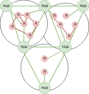
- One mesh network between all supernode / hub nodes. This mesh is "the full view" and can "express" you between any two neighborhoods.
- A rooftop-to-rooftop mesh network within neighborhoods.
- The in-neighborhood meshes will collect all local routes and present them to the hubs.
- Hubs will present all routes from other neighborhoods to each other and to other neighborhoods.
Example Diagram
Mesh argument
A number of people have argued for/against this approach, suggesting this is not a valid mesh layout. While it's true that this is not a traditional "by-the-book" mesh network, it seems mesh communities are all about trying out new things.
Technically we could have used one mesh standard across the entire network, however, a few concerns led us the other direction:
- Some longer running mesh networks have problems moving to newer protocols once too many nodes are deployed. We wanted to avoid this problem by creating smaller interconnected meshes.
- We had difficulting finding cheap and available quality routers to continue building the mesh. Additionally, open firmware project were undergoing internal shifts. Using standard / multiple protocols we can leverage off-the-shelf routers with multiple radios and high speeds; and mix with Libre hardware when available.
- We wanted to support experimentation with multiple protocols in different neighborhoods and interconnectivity to other mesh projects.
Our design is not anti-mesh, but rather embraces the fullness of hardware diversity and interconnectivity.
Network Time Protocol (NTP)
NTP Infrastructure
History: Over the years it has been evolving, changing. We used to use outside NTP servers, from the WWW , then one, and later a second member provided NTP. One via a Stratum-1 server (Antenna getting PPS (Pulse-Per-Second) via two u-blox receivers) the other one as a stratum-2 (chrony). Those 2 members moved on and another member started a new project at his "home lab" to provide NTP stratum-1. We have now setup some NTP servers using chrony and we have the member's project online (GPS PPS NTP/chrony server with a NEO 7M GPS unit on a raspberry Pi.)
Use 10.10.10.123 as your NTP server address.
What is NTP and how did it started?
The Network Time Protocol is a "network" protocol for devices to synch their clocks. See Wiki
How it all started, how does it works, with Dr Julian Onions (University of Nottingham, UK) implementing this after meeting the godfather of Internet time, Dave Mills! Video interview
IP
10.10.10.123 - NTP for the mesh ( Use this one )
NTP stats and status
Here are some stats on the NTP servers:
NTP Server at SN1 (as an example).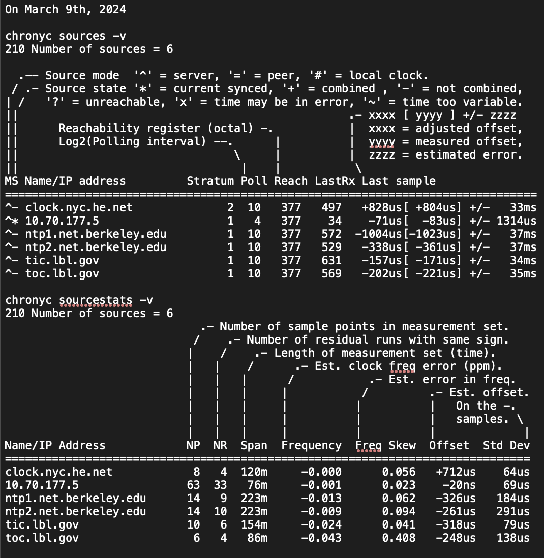
Alternatives
There are many NTP servers on the Net, google offers it, some hardware maker such as Ubiquiti, etc..
Peering
NYC Mesh operates AS395853
Our peering Policy is Yes
Please contact us to peer with our network.
Note this this is our Public ASN, not the Mesh Network itself.
This community-run public network supplies NYC Mesh with net-neutral internet connectivity to support the community. If you would like to join the Mesh Network, please visit our Join Page make use of this network.
Peering Policy
- NYC Mesh has an open peering policy.
- We have no requirements in terms of traffic, size, support/SLA, etc.
- We operate both IPv4 and IPv6. Peering via both protocols is appreciated.
Locations
| Building | Address | Ports |
|---|---|---|
| Sabey | 375 Pearl St, New York, NY | 1G / 10G |
Exchanges
| Exchange | City | IPv4 | IPv6 | ASNs | Routes | Speed |
|---|---|---|---|---|---|---|
| DE-CIX NY | New York, NY | 206.130.10.151 | 2001:504:36::c2ab:0:1 | 105 | ~122K | 1G |
Peering Data
ASN: 395853
IRR AS-SET: AS-NYCMESH
Peering Contact: peering@nycmesh.net
Recommended Max Prefix IPv4: 10
Recommended Max Prefix IPv6: 10
PeerDB Page: https://as395853.peeringdb.com
As we are a non-profit, please consider providing as many routes as possible, including upstream or other routes.
Peers
We have direct peering sessions with the following networks
Thank you to those who have peered!
| ASN | Organization | Exchange |
|---|---|---|
| AS42 | WoodyNet / Packet Clearing House | DE-CIX NY |
| AS714 | Apple Inc. | DE-CIX NY |
| AS3856 | Packet Clearing House | DE-CIX NY |
| AS6939 | Hurricane Electric, Inc. | DE-CIX NY |
| AS9009 | M247 Ltd | DE-CIX NY |
| AS15169 | Google LLC | DE-CIX NY |
| AS20940 | Akamai International B.V. | DE-CIX NY |
| AS27257 | Webair Internet Development Company Inc. | DE-CIX NY |
| AS29838 | Atlantic Metro Communications, LLC | DE-CIX NY |
| AS32217 | GPIEX INC | DE-CIX NY |
| AS33891 | Core-Backbone GmbH | DE-CIX NY |
| AS46450 | Pilot Fiber, Inc. | DE-CIX NY |
| AS53988 | Digi Desert LLC | DE-CIX NY |
| AS54825 | Packet Host, Inc. | DE-CIX NY |
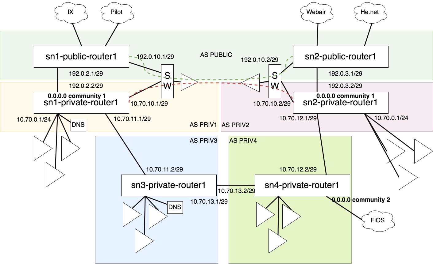
Supernode-Architecture
Goals of this documents
- Supernode routing / goals
- Supernode sample architectures
- Plan to get us to this architecture
Supernode routing / goals
"If you can get to a supernode, you can get to the rest of the mesh ( and the internet )."
- A supernode should be the regional authority on how to get to its region, other regions, and the internet.
- Translate region-local rooftop-to-rooftop protocol routes to standard routes for other regions and vice versa.
- All supernodes should have a full view of all mesh routes.
- Each supernode will get a private ASN in a sequential range with its supernode designation number.
- All routers at the supernode should use BGP confederation and act as a route-reflector.
- A supernode might also run mesh-services that will be announced to the mesh as routes.
- A supernode might provide internet access. If it does, it must:
- Announce a default route prefix internally.
- Translate any private IPv4 to public using NAT. May be CGNAT with a pool of addresses, or single IP
- Translate a specific private IPv6 prefix to public using NPTv6.
- Must tag internet connecting with their source using BGP communities.
- Must not log data nor filter data / routes.
- A supernode might participate in the NYCMesh Public Backbone by using BGP Peering if capable. If so, it will do so in accordance with that architecture.
- Links between supernodes will be routed Layer3 using an IPv4 /24 and IPv6 /64. There will be one VLAN for each link ( site-to-site ). VLANs should not be shared across multiple sites. ( Except in extenuating circumstances or testing crazy things. )
- The reason for this is to allow for multiple routers on each end if appropriate.
Supernode layout
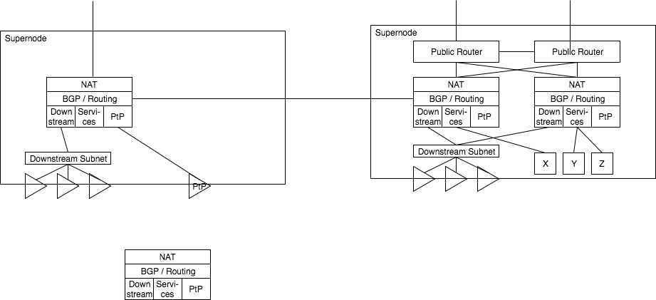 Each supernode has one or more local routers. Each local router has some local subnet, for downstream sector antennas, service nodes, and PtP links. Each router speaks BGP to some of these services and also to neighboring supernodes.
Routers present internet access by passing a NAT layer and consuming some public IP addresses; For example, in a scenario where a single IP connection is handed off, such as Verizon FiOS, the IP is consumed by the NAT services directly.
If the supernode is also a Public Backbone routers, one or more backbone routers provide public access connectivity, with some connectivity being presented to the supernode routers for NAT consumption.
Downstream access can be presented via one or more subnets, one or more antennas, in a mixed fashion for whatever is best for that region.
Each supernode has one or more local routers. Each local router has some local subnet, for downstream sector antennas, service nodes, and PtP links. Each router speaks BGP to some of these services and also to neighboring supernodes.
Routers present internet access by passing a NAT layer and consuming some public IP addresses; For example, in a scenario where a single IP connection is handed off, such as Verizon FiOS, the IP is consumed by the NAT services directly.
If the supernode is also a Public Backbone routers, one or more backbone routers provide public access connectivity, with some connectivity being presented to the supernode routers for NAT consumption.
Downstream access can be presented via one or more subnets, one or more antennas, in a mixed fashion for whatever is best for that region.
Plan to get us to this new architecture
- In our current setup, we present a single subnet directly from our Public Router.
- We should create a second router at Supernode 1 as the supernode router.
- From this new router, we should present several subnets:
- One to Supernode 2
- One to the internal out of band routers
- One or more for downstream client access
- This router should be able to perform NAT for any subnet using a public IP pool
- We should present the Supernode 2 access subnet via a VLAN over the AirFiber 24
- From this new router, we should present several subnets:
- In Brooklyn, we should accept the additional VLAN over the AirFiber and connect it with the router part of the EdgePoint router.
- From there we can setup BGP to accept the routes and also present a default route to Manhattan
- Brooklyn can make several subnets:
- One for internal out of band router access
- One or more for downstream client access
- We can begin to shorten the lease time on the public IPs, switching clients over to private IPs slowly.
- In manhattan, we can begin to use private IPs and public IPs mixed immediately. This subnet will propagate to Brooklyn as well temporarily in-lieu of the Public IPs. As private IPs are found to have no problem, the local private IP subnet can be introduced.
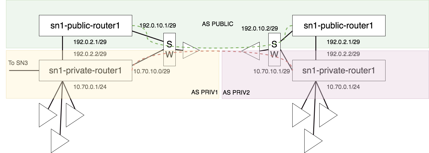
Supernodes interconnecting examples
Virtual Private Network (VPN)
VPN Overview
The NYC Mesh Virtual Private Network (VPN) is a system that enables a computer that is physically disconnected from the rest of the NYC Mesh network (e.g., because it is too distant from existing nodes) to access the network. Put another way, it extends the NYC Mesh network to computers that are not physically part of the mesh. This is used for a number of different purposes, including to provide access to intra-mesh services, ease new node installations, bootstrap new neighborhoods, and more.
A VPN (virtual private networking) is a virtual network, creating a tunnel, or express route, across another network, such as the internet. Within the tunnel the network has no knowledge of the outside network, making it appear as if the entire network is seamless and directly connected. The outside network also has no knowledge of the inside network, making it a safe way to traverse dangerous or unknown networks.
VPN Infrastructure
NYC Mesh maintains some common VPN infrastructure for use by mesh members.
Please feel free to use the VPNs. However, please note that NYC Mesh is not a commercial VPN provider or reseller, nor are we trying to achieve an Internet-based darknet. The VPN service is subject to change and/or breakage at any time. Do not rely on NYC Mesh's VPN service as your primary or critical VPN provider. Also, as with all NYC Mesh resources, do not abuse the VPN service or the access it provides.
When might you use a VPN
We run a VPN service for a variety of reasons. You might want to use the NYC Mesh VPN to:
- tie distant neighborhoods together. For instance, if a distant part of the mesh is too far away from the other nodes to make a reliable physical connection, you can use the VPN to (logically) tie the mesh back together and make intra-mesh services available over the public Internet to the physically separated part of the NYC Mesh network. This isn't required, of course; the distant portion of the mesh can have its own connection to the Internet (an exit node) and maintain itself locally, but without a VPN connection it won't be able to access the rest of the mesh.
- connect your laptop to NYC Mesh over the public Internet. For example, if you are working in a coffee shop but need access to the mesh in order to conduct tests or develop and maintain mesh-specific features, you can connect to the mesh via the VPN. As another example, you can masquerade to Web sites and public Internet services as a NYC Mesh user, so that you can see the Internet from NYC Mesh's "point of view."
- configure networking equipment during an NYC Mesh installation. An installation may involve connecting to another node to configure it, which can be difficult to accomplish without already being on the mesh. By using a VPN connection, an install team member can temporary become part of the mesh prior to the completion of the physical installation.
VPN types and endpoints
Each supernode provides a few VPN options, depending on the supernode's locally available hardware. You may connect to any or all of the supernodes and, in some cases, depending on your hardware, you can even connect to multiple supernodes simultaneously. For the documented currently available endpoints, see § endpoints, below.
Choosing a VPN endpoint
Although you can generally use whatever endpoint you wish, you should consider a combination of factors for the best experience using the NYC Mesh VPN service. These considerations include:
- VPN software support on your computer.
- VPN protocol support provided by the NYC Mesh VPN endpoint.
- Your goal in connecting via the VPN; do you intend to connect a single device (laptop, phone, home router, etc.), or will you do meshing?
Based on these decisions, you will need to choose a different protocol and setup procedure. If your computer does not support any of the VPN protocols our endpoints do, you may need to connect using a different laptop.
Endpoint types
The NYC Mesh VPN service currently offers VPN connectivity using the following protocols.
Each page will list endpoints available for that protocol.
L2TP/IPsec
L2TP/IPSec is a common general-purpose VPN protocol that work with most platforms. For example, computers running Windows, macOS, iPhones, and Android devices all support this type of VPN out-of-the-box. This type of VPN is a little bit oldschool, in that it is typically found in enterprise corporate environments, which is part of what makes it so ubiquitous.
For this reason, we have decided to provide and endpoint of this protocol.
For configuration instructions, please see our L2TP/IPsec page.
WireGuard
WireGuard is a modern type of VPN that was originally developed for Linux. There are now versions of the WireGuard VPN software available for recent Windows, macOS, iPhone, and Android devices as well; however, some older versions of those platforms may not support Wireguard. WireGuard is also typically fast, but is a bit more challenging to set up.
Other VPN types
At this time, we have not set up other VPN types, but we would like to in our spare-time. Other VPN protocols we are considering include: OpenVPN, and VTrunkD.
VPN - L2TP/IPsec
L2TP/IPSec is a common general-purpose VPN protocol that work with most platforms. For example, computers running Windows, macOS, iPhones, and Android devices all support this type of VPN out-of-the-box. This type of VPN is a little bit oldschool, in that it is typically found in enterprise corporate environments, which is part of what makes it so ubiquitous. For this reason, we have decided to provide and endpoint of this protocol.
Technically speaking, it is a combination of L2TP and IPsec protocol standards. The former protocol (L2TP, the Layer 2 Tunneling Protocol) carries a "call" over the Internet, while the latter protocol suite (IPsec, Internet Protocol Security) encrypts the call and authenticates the participants. Although it's possible to use either protocol without the other, L2TP and IPsec are most often used together. This is because L2TP creates a connection but does not secure the connection, while IPSec protects traffic but does not itself create a network connection to carry traffic.
L2TP/IPsec VPNs are often slower than more modern protocols because the implementation on smaller routers is usually implemented in software which makes heavy use of the router's CPU. On the other hand, more expensive routers often have a custom chip to speed-up IPSec encryption, actually making L2TP/IPsec the fastest choice in certain cases.
The best performance you can reasonably expect from on small routers is around ~100Mbps.
Device support
The L2TP/IPsec protocol enjoys very wide support across platforms and vendors.
- Windows devices: Should work - Guide Here
- Apple devices: iPhones, Mac laptops, natively - iOS Guide Here, macOS Guide Here
- Android devices: Most yes - Guide Here
- Linux: Yes, complicated without GUI, works well with Network Manager - Guide Here
- Ubiquiti EdgeOS: Yes, but slow - Guide Here
- Mikrotik devices: All ( various speeds ) - No Guide Yet
- OpenWRT: Should work - No Guide Yet
Endpoints
This section provides connection information for NYC Mesh VPN endpoints that use L2TP/IPsec.
Supernode 1
- Server domain name:
l2tpvpn.sn1.mesh.nycmesh.net - Supported connection methods:
- Anonymous:
- Username:
- Password:
- Pre-shared key/secret:
- OSPF Node-Peering (Same, connect as above, use OSPF afterwards.)
- Anonymous:
Supernode 3
- Server domain name:
l2tpvpn.sn3.mesh.nycmesh.net - Supported connection methods:
- Anonymous:
- Username:
- Password:
- Pre-shared key/secret:
- OSPF Node-Peering (Same, connect as above, use OSPF afterwards.)
- Anonymous:
Account
N.B. Your account will be specific to SN1 or SN3 - note in the comments if you have a preference
Connection Guides
Please follow the below connection guides for each platform.
Windows 10
Expand to view instructions...
- Click on Start (Title menu) and type VPN
- Click on on Change Virtual Private Networks (VPN)
- Click on the plus button (Add a VPN connection)
- Choose VPN provider (Microsoft by default)
- Connection name (Name it whatever you want)
- Server name or address
l2tpvpn.sn1.mesh.nycmesh.net - VPN Type: L2TP/IPsec with pre-shared key
- Pre-shared key:
nycmeshnet - Type of sign-in info: User name and password
- Username:
your personal user name - Password:
your personal password - Check box to remember password so you don't have to type this everytime
- Click save
- Click on newly created VPN connection and click connect
macOS
Expand to view instructions...
See Apple Support: Set up a VPN Connection. Be sure to use the appropriate authentication credentials for your connection. For an anonymous connection, enter your personal user name as the "account name" and your personal user name in the User Authentication's "password" field and 'nycmeshnet' the Machine Authentication's "Shared Secret" field.
Apple iOS
Expand to view instructions...
These instructions refer to Apple-branded handheld devices such as the iPhone and iPad.
- Go to Settings
- Tap on VPN
- Tap on Add VPN Configuration
- Tap on Type and choose L2TP
- Description (Anything you want)
- Server:
l2tpvpn.sn1.mesh.nycmesh.net - Account:
your personal user name - Leave RSA SecurID off
- Password
your personal password - Secret:
nycmeshnet
Android
Expand to view instructions...
See How-To Geek: How to Connect to a VPN on Android § Android’s Built-In VPN Support.
GNU/Linux - GNOME/Network Manager
Expand to view instructions...
Using GNOME/Network Manager:
- Make sure you have the L2TP/IPsec NetworkManager plugin installed (
NetworkManager-l2tp-gnomeon Fedora) - Add a new VPN of type 'Layer 2 Tunneling Protocol'
- Gateway:
l2tpvpn.sn1.mesh.nycmesh.net - Username:
your personal user name - Password:
your personal passwrod(you may have to click a question mark on the right of the textbox to allow saving the password) - Click "IPsec Settings"
- Check "Enable IPsec tunnel to L2TP host"
- Pre-shared key:
nycmeshnet - Save & Connect
Ubiquiti EdgeOS
Expand to view instructions...
This example EdgeRouter configuration will let clients on your LAN reach the mesh. It requires at least EdgeOS 2.0.9 which adds support for connecting to L2TP/IPsec VPNs. You will need to be familiar with the EdgeOS CLI.
Note: there is a bug in EdgeOS's PPP configuration that prevents EdgeRouter from connecting to the NYC Mesh VPN. Make sure to configure the workaround scripts on your EdgeRouter.
Here is a minimal configuration for connecting to the Supernode 1 VPN.
First, enter configuration mode:
configure
Then, configure the L2TP client interface (you should be able to copy and paste all the lines in this block at once):
set interfaces l2tp-client l2tpc0 server-ip l2tpvpn.sn1.mesh.nycmesh.net
set interfaces l2tp-client l2tpc0 description "NYC Mesh VPN (SN1)"
set interfaces l2tp-client l2tpc0 authentication user-id 'your personal user name'
set interfaces l2tp-client l2tpc0 authentication password your personal password'
set interfaces l2tp-client l2tpc0 require-ipsec
Next, configure the IPsec tunnel:
set vpn ipsec esp-group NYC_MESH mode transport
set vpn ipsec esp-group NYC_MESH pfs disable
set vpn ipsec esp-group NYC_MESH proposal 1 encryption aes256
set vpn ipsec esp-group NYC_MESH proposal 1 hash sha1
set vpn ipsec ike-group NYC_MESH dead-peer-detection action restart
set vpn ipsec ike-group NYC_MESH proposal 1 encryption aes256
set vpn ipsec ike-group NYC_MESH proposal 1 hash sha1
set vpn ipsec site-to-site peer l2tpvpn.sn1.mesh.nycmesh.net description "NYC Mesh VPN (SN1)"
set vpn ipsec site-to-site peer l2tpvpn.sn1.mesh.nycmesh.net authentication mode pre-shared-secret
set vpn ipsec site-to-site peer l2tpvpn.sn1.mesh.nycmesh.net authentication pre-shared-secret nycmeshnet
set vpn ipsec site-to-site peer l2tpvpn.sn1.mesh.nycmesh.net local-address default
set vpn ipsec site-to-site peer l2tpvpn.sn1.mesh.nycmesh.net ike-group NYC_MESH
set vpn ipsec site-to-site peer l2tpvpn.sn1.mesh.nycmesh.net tunnel 1 esp-group NYC_MESH
set vpn ipsec site-to-site peer l2tpvpn.sn1.mesh.nycmesh.net tunnel 1 local port l2tp
set vpn ipsec site-to-site peer l2tpvpn.sn1.mesh.nycmesh.net tunnel 1 protocol udp
set vpn ipsec site-to-site peer l2tpvpn.sn1.mesh.nycmesh.net tunnel 1 remote port l2tp
Here's what your final configuration should look like. You can view it with show interfaces l2tp-client and show vpn. There are more settings here than you typed in above. That's ok. The additional settings are part of the default L2TP/IPsec config.
interfaces {
l2tp-client l2tpc0 {
authentication {
password 'your personal password'
user-id your personal user name'
}
default-route auto
description "NYC Mesh VPN (SN1)"
mtu 1400
name-server auto
require-ipsec
server-ip l2tpvpn.sn1.mesh.nycmesh.net
}
}
vpn {
ipsec {
allow-access-to-local-interface disable
auto-firewall-nat-exclude disable
esp-group NYC_MESH {
compression disable
lifetime 3600
mode transport
pfs disable
proposal 1 {
encryption aes256
hash sha1
}
}
ike-group NYC_MESH {
dead-peer-detection {
action restart
interval 30
timeout 120
}
ikev2-reauth no
key-exchange ikev1
lifetime 28800
proposal 1 {
dh-group 2
encryption aes256
hash sha1
}
}
site-to-site {
peer l2tpvpn.sn1.mesh.nycmesh.net {
authentication {
mode pre-shared-secret
pre-shared-secret nycmeshnet
}
connection-type initiate
description "NYC Mesh VPN (SN1)"
ike-group NYC_MESH
ikev2-reauth inherit
local-address default
tunnel 1 {
allow-nat-networks disable
allow-public-networks disable
esp-group NYC_MESH
local {
port l2tp
}
protocol udp
remote {
port l2tp
}
}
}
}
}
}
PPP configuration workaround
There is a bug in EdgeOS's PPP configuration that prevents EdgeRouter from connecting to the NYC Mesh VPN. Before you commit your VPN configuration, add the following scripts to your EdgeOS device:
The first script is located at /config/scripts/post-config.d/post-commit-hooks.sh. It's a helper that lets you run scripts every time you commit a new configuration.
#!/bin/sh
set -e
if [ ! -d /config/scripts/post-commit.d ]; then
mkdir -p /config/scripts/post-commit.d
fi
if [ ! -L /etc/commit/post-hooks.d/post-commit-hooks.sh ]; then
sudo ln -fs /config/scripts/post-config.d/post-commit-hooks.sh /etc/commit/post-hooks.d
fi
run-parts --report --regex '^[a-zA-Z0-9._-]+$' /config/scripts/post-commit.d
Make it executable and then run it:
chmod +x /config/scripts/post-config.d/post-commit-hooks.sh
/config/scripts/post-config.d/post-commit-hooks.sh
The second script fixes the PPP configuration for your L2TP tunnel so that you can successfully connect. It is located at /config/scripts/post-commit.d/fixup-l2tpc0.sh. Note: this is a different directory from the previous script.
#!/bin/bash
set -e
DEVICE=l2tpc0
CONFIG=/etc/ppp/peers/$DEVICE
if [ ! -f $CONFIG ]; then
exit
fi
if grep ^remotename $CONFIG > /dev/null; then
exit
fi
echo "remotename xl2tpd" | sudo tee -a $CONFIG > /dev/null
Make it executable:
chmod +x /config/scripts/post-commit.d/fixup-l2tpc0.sh
MTU workaround
Additionally, EdgeOS has a bug where pppd fails to correctly set the MTU of the L2TP interface. This is a problem if you plan to use OSPF over the VPN because OSPF requires that both peers agree on an MTU.
This script, located at /config/scripts/ppp/ip-up.d/l2tp-fix-mtu works around this issue by manually setting the MTU after the connection comes up.
#!/bin/sh
set -e
MTU=$(grep mtu /etc/ppp/peers/$PPP_IFACE | awk '{ print $2 }')
if echo $PPP_IFACE | grep -Eq ^l2tpc[0-9]+; then
ip link set dev $PPP_IFACE mtu $MTU
fi
Make it executable, and commit your configuration:
chmod +x /config/scripts/ppp/ip-up.d/l2tp-fix-mtu
commit
If all goes well, you should be connected to the VPN and be able to reach the other end of the tunnel:
ubnt@edgerouter# run show interfaces l2tp-client
Codes: S - State, L - Link, u - Up, D - Down, A - Admin Down
Interface IP Address S/L Description
--------- ---------- --- -----------
l2tpc0 10.70.72.68 u/u NYC Mesh VPN (SN1)
ubnt@edgerouter# ping 10.70.72.1
PING 10.70.72.1 (10.70.72.1) 56(84) bytes of data.
64 bytes from 10.70.72.1: icmp_seq=1 ttl=64 time=6.15 ms
64 bytes from 10.70.72.1: icmp_seq=2 ttl=64 time=6.42 ms
64 bytes from 10.70.72.1: icmp_seq=3 ttl=64 time=4.98 ms
^C
--- 10.70.72.1 ping statistics ---
3 packets transmitted, 3 received, 0% packet loss, time 2007ms
rtt min/avg/max/mdev = 4.985/5.854/6.424/0.627 ms
Additionally, the MTU of your L2TP interface should be correctly set to 1400:
ubnt@edgerouter# ip link show l2tpc0
34: l2tpc0: <POINTOPOINT,MULTICAST,NOARP,UP,LOWER_UP> mtu 1400 qdisc pfifo_fast state UNKNOWN mode DEFAULT group default qlen 100
link/ppp
Save your active configuration to the startup configuration so that your tunnel will still be there when you reboot, and exit configuration mode:
save
exit
Reaching the mesh through the VPN
So far, your EdgeRouter can reach the VPN server at the other end of the tunnel, but you can't reach any of the other devices on the mesh (try pinging 10.10.10.10; you shouldn't be able to reach it). You can fix this by OSPF peering or by adding a static route. A static route is easiest.
In configuration mode, enter the following, and commit it:
set protocols static interface-route 10.0.0.0/8 next-hop-interface l2tpc0 description "NYC Mesh"
In this configuration, your EdgeRouter will route traffic destined for the mesh's private IP network through the VPN and all your other traffic over your primary internet connection – this is sometimes called split VPN. If you use addresses from 10.0.0.0/8 for your LAN that overlap with addresses used by the mesh, the addresses on your LAN will take precedence and you will not be able to access those parts of the mesh.
Once you've installed the static route, you should be able to reach the rest of the mesh:
ubnt@edgerouter# ping 10.10.10.10
PING 10.10.10.10 (10.10.10.10) 56(84) bytes of data.
64 bytes from 10.10.10.10: icmp_seq=1 ttl=63 time=4.85 ms
64 bytes from 10.10.10.10: icmp_seq=2 ttl=63 time=4.28 ms
64 bytes from 10.10.10.10: icmp_seq=3 ttl=63 time=7.08 ms
^C
--- 10.10.10.10 ping statistics ---
3 packets transmitted, 3 received, 0% packet loss, time 2006ms
rtt min/avg/max/mdev = 4.286/5.408/7.082/1.207 ms
Remember to save your configuration to the startup config once it's working.
Using NAT to reach the mesh from a device on your network
You can now reach the mesh from your EdgeRouter, but you can't reach it from a device on your LAN like your laptop. The easiest way to do this is to use NAT:
set service nat rule 6000 outbound-interface l2tpc0
set service nat rule 6000 type masquerade
set service nat rule 6000 description "masquerade for NYC Mesh (SN1)"
Commit your config, and verify that you can reach the mesh from your laptop:
me@laptop$ ping 10.10.10.10
PING 10.10.10.10 (10.10.10.10): 56 data bytes
64 bytes from 10.10.10.10: icmp_seq=0 ttl=62 time=13.572 ms
64 bytes from 10.10.10.10: icmp_seq=1 ttl=62 time=10.603 ms
64 bytes from 10.10.10.10: icmp_seq=2 ttl=62 time=16.394 ms
^C
--- 10.10.10.10 ping statistics ---
3 packets transmitted, 3 packets received, 0.0% packet loss
round-trip min/avg/max/stddev = 10.603/13.523/16.394/2.364 ms
Once your configuration is working, save it to your startup config.
If you can ping 10.10.10.10 from the router, but not other devices on your LAN, you may need to reboot the router to clear the route cache.
Configuring .mesh DNS lookup
To use the .mesh top level domain to reach mesh services, you will need to change the DNS configuration on your EdgeRouter. The simplest way to do this is to configure your router's DHCP server to tell clients to use the mesh's recursive resolver (10.10.10.10) as their DNS server. But this causes a problem with our split VPN config: if your VPN connection goes down, you won't be able to resolve domain names, even if you're still connected to the public internet.
To fix this, you can configure EdgeOS's DNS forwarder to use the mesh's authoritative name server (10.10.10.11) for the .mesh TLD:
set service dns forwarding options server=/mesh/10.10.10.11
Additionally, you can configure the DNS forwarder to use the mesh's name server for reverse DNS lookups on 10.0.0.0/8:
set service dns forwarding options rev-server=10.0.0.0/8,10.10.10.11
Make sure to configure the DHCP server to provide your router's LAN address as the recursive DNS resolver.
To be able to reach the .mesh TLD while SSH'd into your EdgeRouter, configure your EdgeRouter to use its local DNS forwarder as its primary DNS server:
set system name-server 127.0.0.1
VPN - WireGuard
WireGuard is a new, simple, and fast VPN implementation and protocol. For comparison, the older L2TP/IPsec VPNs typically will achieve about 100Mbps, but WireGuard VPNs may reach speeds upward of 300-400Mbps on the same hardware, or higher on a high-end workstation.
In addition to its speed, WireGuard has some great features such as built-in roaming (a single encrypted packet moves the tunnel to your new IP), cryptokey routing, and formal cryptographic verification.
On the other hand, it also has some challenges, such as pre-key exchange and a lack of automatic address assignment. Both of these problems require manual configuration on both ends of the tunnel. Cryptokey routing also presents its own challenges in some situations.
A WireGuard VPN is best suited for connecting single end-user devices such as laptops and phones to the mesh over the internet from a location that has no mesh access.
Routing over WireGuard
WireGuard, like other VPNs, can be used in conjunction with a routing protocol, such as OSPF which we use in NYC Mesh. However, there are some challenges with WireGuard and routing.
These challenge are highlighted on another page, as it is a longer and more technical discussion.
Please see VPN - WireGuard + OSPF
Device support
WireGuard implementations are being developed on a variety of platforms. The following list provides an overview, but see the WireGuard Installation instructions for further details.
- Linux: Yes!
- Android devices: Yes, some - See WireGuard website
- OpenWRT: Yes, in LEDE on latest versions, in certain builds
- Apple devices: Yes, some - See Wireguard website
- Mikrotik devices: Starting in RouterOS 7.1beta2
- Ubnt routers: No (well, technically yes, but the module has caused lots of problems, so please don't use it yet)
- Windows devices: Yes, some - See WireGuard website
Endpoints
Supernode 1:
- IPv4/6:
wgvpn.sn1.mesh.nycmesh.net:51820 - Supported connect methods:
- End Device
OSPF - Not YetBGP Node-Peering - Now legacy, please do not use
Supernode 3:
- IPv4/6:
wgvpn.sn3.mesh.nycmesh.net:51820 - Supported connect methods:
- End Device
- OSPF Node-Peering
How To Connect
Connecting end-devices
- Ensure WireGuard will work on your device
- Generate a Wireguard public key, and give it to Zach. (https://www.wireguard.com/quickstart/#key-generation)
- Zach will give you the server public key and assign you an IP address. This will change later, but just for now to get the docs out, this is what we currently do.
VPN Request Proceedure
NYC Mesh maintains some common VPN infrastructure for use by active mesh members.
Please feel free to use the VPNs. However, please note that NYC Mesh is not a commercial VPN provider or reseller, nor are we trying to achieve an Internet-based darknet. The VPN service is subject to change and/or breakage at any time. Do not rely on NYC Mesh’s VPN service as your primary or critical VPN provider. Also, as with all NYC Mesh resources, do not abuse the VPN service or the access it provides.
How to request a NYC Mesh VPN connection:
Please write to "vpn @ nycmesh.net" and provide the following information, the same you provided on the join request form, to register your install.
-
First name:
-
Last name:
-
Phone number:
-
Location (street address, including zip code):
-
Email:
-
Active Install number:
-
Comment:*
*please indicate if it is to be used by you, from your laptop, phone, etc.. Or if it is to be setup on your node, such as for a "remote node" or else.
A volunteer will reach out with a response to your request.
Please note, for network security purposes we generally deny requests for remote access to the network by people who are not existing mesh members or who do not live in the New York City metropolitan area. If you feel like you have a valid reason to request VPN access but your request has been denied, please reach out on Slack for assistance.
WireGuard VPN Setup Guide
- Originally written by JohnB in 2024-09
- This is an attempt to document the setup process and the lessons from that process, both for setting up a personal phone connection to the Mesh as well as setting up an Omni in Queens that connects back to the Mesh via VPN
- A note on permissions: You will need someone with write access to the IPRanges Google Spreadsheet, where the Mesh keeps track of all the different in-use IP addresses/networks/subnets. You will also need root access to the SN1 and/or SN3 VPN instances in order to edit files on them to support your connection
SN1 "Road Warrior" Remote Access for Phone
- WireGuard app 1.0.20231018 running on Android 14
- Usage: This type of setup allows for remote access of NYC Mesh IP addresses for remote debugging, Mesh access while on a rooftop independent of that rooftop to avoid bridge filter or other issues, and so on. This is a sort of hub-and-spoke setup where one WireGuard tunnel on the server will have many peers in the field
- Example configuration values
- IPRanges spreadsheet reservation
10.70.73.0/24has enough remaining room for many more setups - WireGuard phone tunnel IP
10.70.73.69used here for the phone/laptop for demonstration purposes. Note that it is part of the subnet above - WireGuard server SSH IP
10.42.43.42 - WireGuard server public IP/Endpoint
199.167.59.4with port51822 - WireGuard server tunnel private key
[redacted]and public key04crAKqAju+ZlEXCdZGAa4OyhDe1k2CHIlshr2KoYAQ= - WireGuard phone tunnel private key
CIHyP1xYRh3zl7bE6XYsXXFhrf8CXjn4mlIkEdfLAE0=and public key6jzT2XA7IX2E8htpWP9qJIGUzhjkFESFqvFowNVj5Xw=
- IPRanges spreadsheet reservation
Phone Setup
- Install the WireGuard app
- Create a new tunnel from scratch
- Add an Interface Name of something similar to MESHSN1
- Generate a Private key, for example
CIHyP1xYRh3zl7bE6XYsXXFhrf8CXjn4mlIkEdfLAE0=. This will also generate a corresponding Public key6jzT2XA7IX2E8htpWP9qJIGUzhjkFESFqvFowNVj5Xw=which should be noted down for the server setup later - Add an Interface Address, such as
10.70.73.69/32. The specific IP will be different from device to device, but the /32 should always be present so the phone always uses the exact address listed - Add an Interface DNS server of
10.10.10.10, which is the Mesh DNS server - Add a Peer at the bottom to show more entry fields
- Add the WireGuard server tunnel public key to the Peer Public key field, for example
04crAKqAju+ZlEXCdZGAa4OyhDe1k2CHIlshr2KoYAQ= - Add the WireGuard server public IP/endpoint with port to the Endpoint field, for example
199.167.59.4:51822 - Add
0.0.0.0/0to the Allowed IPs field to route all traffic on the device through the WireGuard tunnel- Allowed IPs means the "range of IP addresses to be routed to the SN1 WireGuard Tunnel"
- To only send Mesh traffic through the tunnel, instead enter
10.0.0.0/8,199.168.59.0/24,199.170.132.0/24,23.158.16.0/24. These are the IP ranges commonly considered "Mesh" IPs, and are deployed as part of the default Mesh device configuration https://configgen.nycmesh.net/
- Push the Save button, and then enable the new configuration
- When the configuration is functional, open it and look for the "Latest handshake" at the bottom, as well as "Transfer" statistics showing the transmitted and received bytes
- The configuration can also be added as a file. Here's an example of how the file might look:
[Interface]
Address = 10.70.73.69/32
DNS = 10.10.10.10
PrivateKey = CIHyP1xYRh3zl7bE6XYsXXFhrf8CXjn4mlIkEdfLAE0=
[Peer]
AllowedIPs = 0.0.0.0/0
Endpoint = 199.167.59.4:51822
PublicKey = 04crAKqAju+ZlEXCdZGAa4OyhDe1k2CHIlshr2KoYAQ=
SN1 Server Setup
- SSH to the SN1 VPN1 WireGuard server with
ssh support@10.42.43.42from inside the Mesh. Runsuto gain root access - Edit the
/etc/wireguard/wg2.confto add new lines to the bottom containing the new WireGuard Peer. Pick a new IP that has not already been used in the file while still being in the range of the subnet- Multiple WireGuard files and interfaces exist, but this
wg2tunnel is specifically for remote access and is the only place that needs editing - The PublicKey line is the phone tunnel public key
- The AllowedIPs line is to list the specific IPs that are able to pass traffic to and from WireGuard. In other words, Allowed IPs means "the range of accepted peer interface IP addresses for this particular peer." In this case a /32 and a specific address are used to ensure each remote access can only connect from a single IP. Otherwise, if a /24 or /0 were used, it's possible for multiple peers to assume the first IP in the range and then have address conflicts.
- Multiple WireGuard files and interfaces exist, but this
# JohnB phone
[Peer]
PublicKey = 6jzT2XA7IX2E8htpWP9qJIGUzhjkFESFqvFowNVj5Xw=
AllowedIPs = 10.70.73.69/32
- Disable and re-enable the network interface this WireGuard tunnel is connected to with
ifdown --force wg2and thenifup wg2- This works because a configuration exists at
/etc/network/interfacesfor thewg2interface to perform actions before, during, and after taking the interface online or offline - This also works because the
wg2.conffile specifies a ListenPort of 51822, and that port is open in the firewall usingiptables. The rules can be viewed withiptables -S
- This works because a configuration exists at
- That's it! By adding a few lines and cycling the interface, the WireGuard server interface is ready to accept the phone's incoming connection
- The command
wg show wg2 latest-handshakescan be run to see the timestamp of each peer's last connection. If a peer hasn't connected, a timestamp of0will be shown, otherwise a working connection should have a timestamp such as1727705817-
wg show wg2 transferwill show the traffic amounts for each peer -
wg show wg2 allowed-ipswill show all the peer IP addresses
-
Alternate pfSense Setup
- This section is for connecting a home pfSense router to the Mesh for general Mesh IP access from any device behind it.
- Install the WireGuard package from System/Package Manager
- Go to VPN/WireGuard/Settings and change Interface Group Membership to "Only Unassigned Tunnels"
- Go to VPN/WireGuard/Tunnels and create a new tunnel. Generate a new keypair and note down the Public key for later. Let's assume in this case that it's the same as the phone setup above, with public key
6jzT2XA7IX2E8htpWP9qJIGUzhjkFESFqvFowNVj5Xw=. Save the tunnel - Go to VPN/WireGuard/Peers and create a new peer. Set its tunnel to the tunnel that was just created. Uncheck the Dynamic Endpoint. Set the Endpoint to the SN1 public IP
199.167.59.4with port51822. Set the Keepalive to 25 seconds (TBD whether this is necessary). Set the Public Key to the SN1 WireGuard server tunnel public key04crAKqAju+ZlEXCdZGAa4OyhDe1k2CHIlshr2KoYAQ=. Set the allowed IPs to the NYC Mesh Internal IPs,10.0.0.0/8,199.168.59.0/24,199.170.132.0/24, and23.158.16.0/24 - Go to Interfaces/Assignments and pick the new WireGuard tunnel in the Available Network Ports and then hit "Add"
- Let the page reload and then click on the new OPT4 interface that was created for the WireGuard tunnel. Change its name to something descriptive such as MESHSN1, set its IPV4 to be Static, set the MTU to something lower than 1500 (1200 works, maybe 1344/1366 works), and then set the IPV4 address to the phone tunnel IP,
10.70.73.68/24. Note the /24 is important here so the interface is aware of the entire subnet. In this case, this will not assign a random IP inside the /24. Make sure the block networks is turned off, and then save. - Now go to System/Routing/Gateways and add a new Gateway. Pick the MESHSN1 interface created before, set the Gateway to the IP of the SN1 tunnel, in this case
10.70.73.1. Save the Gateway - Now go to System/Routing/Static Routes and add new Static Routes for each of the NYC Mesh Internal IPs,
10.0.0.0/8,199.168.59.0/24,199.170.132.0/24, and23.158.16.0/24, with the Gateway set to the MESHSN1 gateway created earlier - Now go to Firewall/Rules and pick the tab of the name of the Interface created earlier, in this case MESHSN1. Do not go to the WireGuard tab, that is irrelevant here. Once at the MESHSN1 Rules tab, add a new rule that Passes IPv4 traffic of Any protocol from Any source to Any destination, on interface MESHSN1. This will pass VPN traffic from WireGuard peers out to other interfaces
- At this point, the WireGuard tunnel should be online and able to pass traffic from any device connected through pfSense.
- The status of the VPN link can be checked in Status/WireGuard and expanding the tunnel to see the latest handshake, the RX, and the TX
- Go to Diagnostics/Routes to see the routes assigned to the new WireGuard tunnel
- Go to Status/Gateways to see whether the MESHSN1 gateway is Online and what the round trip latency is to the endpoint
SN3 OSPF MikroTik Access
- MikroTik RouterOS 7.16 running on an OmniTIK 5 ac
- Usage: This type of setup is reserved for expanding the Mesh, as new nodes can connect to the WireGuard node and advertise OSPF routes that are connectable from the rest of the Mesh. This sort of setup requires a separate WireGuard tunnel and network interface on the server for each new WireGuard peer connection.
- Example configuration values
- Mesh Network Number
666 - OmniTIK 5 ac port 1 connected to Verizon Fios router. Fios Router gateway/internal IP is
10.1.102.1, the subnet is10.1.102.0/24and Omni DHCP IP is10.1.102.100 - IPRanges spreadsheet reservation is the
10.70.251.120/30subnet/network. Note that a /31 will not work with Mikrotik devices. Note that the range must be unique across the Mesh - WireGuard SN3 tunnel IP is
10.70.251.121. Note that it is part of the subnet above - WireGuard Omni tunnel IP is
10.70.251.122. Note that it is part of the subnet above - WireGuard SN3 server SSH IP
199.170.132.4 - WireGuard SN3 server public IP/Endpoint
199.170.132.4with port51841 - WireGuard SN3 server tunnel private key
UOh8LbR8N0LFSQR57J8F1PN0v9xr+kFT/nS6zkQK4Go=and public keyquKdVkH8qRNaJ/JwgQ8bIob5OwKtxSf9BrdN3Kgx5UE= - WireGuard Omni tunnel private key
sAUBqTCSAAfoqna9F9lqRbc7t8W4xFFOfsoKQjbbbGo=and public keyJFVGiXzPEQWBZTTJsYbgLl17zYPFrzgr5d+ZtAHV0kg=
- Mesh Network Number
MikroTik Setup
- First generate and download a config from https://configgen.nycmesh.net/?version=testing&device=Omnitik5AC while entering the network number, in this case
666- Note that the template is
omni-only-ros7.rsc.tmplwhich in other words is a template prepared for RouterOS 7 OmniTIK 5 ac or OmniTIK 5 PoE ac devices - Note that the config can be applied to other devices, but the specific interfaces and beeps may need to be modified depending on the target device's hardware
- Note that the template is
- Update to the latest RouterOS 7 Stable release, which as of writing is 7.16. This can be done in System/Packages and "Check for Updates" and then "Download&Install"
- Apply the config to the device. This may be most easily done by performing the following:
- Upload the config by going to Files and then Upload and picking the
omni-only-ros7.rscfile downloaded earlier - Go to System/Reset Configuration, check the "Keep users" and "No Default Configuration" options, and then picking the
omni-only-ros7.rscfile in the "Run after Reset" box - Hit the "Reset Configuration" button and then wait five minutes for the Kernkraft 400 song to play
- Upload the config by going to Files and then Upload and picking the
- Begin making modifications for the WireGuard setup:
- Remove port1/ether1 from the Mesh bridge so it can be used to get Internet access and DHCP from the Fios router. Go to Bridge/Ports and push the "Remove" button next to
ether1 - Add a DHCP client to ether1 so it can get Internet access. Go to IP/DHCP Client, hit "New" and set the Interface to
ether1and then make sure the "Add Default Route" is set to No. Hit OK and the DHCP-assigned IP should now show here, as well as in the IP/Addresses page- Note: The default route is what allows the Omni to get raw internet access through the Fios router, but it will conflict with the OSPF default route to be added later and cause the WireGuard connection to flap
- Add a WireGuard Tunnel.
- Name it
nycmesh-sn3-wg-vpn - Set the MTU to
1344. The MTU is an open question of optimization. The default RouterOS provides is 1420, but Mesh configs seem to often use 1366 or 1344. The smaller the number, the less chance there is of packet fragmentation, but the greater chance of slower speeds because of less data per packet - Hit OK.
- Reopen the newly created tunnel and note down its Public Key, for example
JFVGiXzPEQWBZTTJsYbgLl17zYPFrzgr5d+ZtAHV0kg=
- Name it
- Add an IP to the WireGuard Tunnel interface
- Go to IP/Addresses and create a New Address
- Set the Address to the IP reserved for the Omni end of the tunnel, in this case
10.70.251.122/30. - Set the Network to the beginning of the IP range set aside for this Tunnel, in this case
10.70.251.120 - Set the Interface to
nycmesh-sn3-wg-vpn
- Add a WireGuard Peer to the Tunnel. Go to the WireGuard/Peers tab and hit "New"
- Set the interface to
nycmesh-sn3-wg-vpn - Set the public key to the WireGuard server tunnel public key, such as
quKdVkH8qRNaJ/JwgQ8bIob5OwKtxSf9BrdN3Kgx5UE= - Set the endpoint to the SN3 public IP
199.170.132.4 - Set the Endpoint Port to the chosen port, such as
51841 - Set the Allowed Address to
0.0.0.0/0which will route all traffic through this WireGuard Peer - Set the Persistent Keepalive to 25 seconds. This is an open question of whether it is necessary or not. Presumably it's there because it was needed, as the WireGuard default is to have no Persistent Keepalive
- Hit OK to save the Peer
- Set the interface to
- Now configure OSPF Interface Templates. Go to Routing/OSPF and the Interface Templates tab, and hit "New"
- Set the Interface to
nycmesh-sn3-wg-vpn - Set the Network to the subnet reserved for this tunnel, in this case
10.70.251.120/30 - Set the Network Type to
ptmp - Set the Cost to the chosen value for this link, in this case
100 - Set the Priority to 1
- Set the Auth ID to 1
- Hit OK to save
- Set the Interface to
- Now configure an OSPF Static Neighbor. Go to Routing/OSPF and the Static Neighbor tab, hit "New" and then fill out the Address, which should be a combination of the SN3 tunnel IP and the Omni WireGuard interface name, in this case
10.70.251.121%nycmesh-sn3-wg-vpn - Now configure a Static Route that tells the Omni to route traffic destined for the SN3 public IP to the Fios gateway, not through the WireGuard tunnel.
- Go to IP/Routes and hit "New"
- Set the Destination Address to the SN3 public IP plus a /32, in this case
199.170.132.4/32 - Set the Gateway to the Fios router's gateway/internal IP, in this case
10.1.102.1 - Add a Distance and set it to 1, representing an OSPF cost of 1
- Note: If this route were not in place: The tunnel link would come online, it would advertise the 0.0.0.0/0 default route, all traffic would be routed through the tunnel INCLUDING the WireGuard-wrapped traffic, and then the tunnel link would drop because it's trying to send its traffic inside itself
- Note: If this gateway IP changes, say when the DHCP client on ether1 gets a new lease, this Static Route will have to be updated manually. Until that point, the WireGuard link will function for traffic inside the Mesh but no public Internet traffic
- Now configure a Route Filter that prevents the Fios LAN subnet from being advertised via OSPF. Go to Routing/Filters and hit "New"
- Set the Chain to
ospf-out - Set the Rule to the Fios router's LAN subnet, in this case
if (dst in 10.1.102.0/24) {reject;} - Hit "OK"
- Then click and drag to re-order this rule to sit above the
ospf-out acceptrule
- Set the Chain to
- At this point, assuming the SN3 side is set up, the tunnel should be functional. Some of the tests that can be performed:
- Go to the WireGuard Tunnel
nycmesh-sn3-wg-vpnand scroll down to its Traffic section to see if traffic is flowing in both directions - Go to the WireGuard Peer and scroll down to see the Last Handshake, as well as the Rx and Tx traffic counts
- Ping the SN3 tunnel's IP address
10.70.251.121or Google's DNS IP8.8.8.8or another Mesh node such as10.69.5.84with Tools/Ping - Try to resolve DNS by running
put [resolve google.com]in the Terminal - Observe the Log to ensure there aren't WireGuard flaps causing OSPF to cycle between down, init, and full (also visible in Routing/OSPF/Neighbors)
- Plug a device into one of ether2 thru ether5, or connect to the Community Wifi SSID, and see if it gets internet
- Go to the WireGuard Tunnel
Below is an example of the full config pulled from the Omni, scrubbed of PII. Note that this config is specific to NN666, and cannot be copypasta'd to another device without modification of IP ranges, addresses, keys, etc.
# 2024-09-30 14:27:44 by RouterOS 7.17beta2
# software id = 12345
#
# model = RBOmniTikG-5HacD
# serial number = 12345
/interface bridge add fast-forward=no name=mesh protocol-mode=none
/interface bridge add fast-forward=no name=wds protocol-mode=none
/interface ethernet set [ find default-name=ether1 ] comment="JohnB home Fios uplink for WireGuard"
/interface wireguard add comment="SN3 WireGuard" listen-port=13231 mtu=1344 name=nycmesh-sn3-wg-vpn
/interface wireless security-profiles set [ find default=yes ] supplicant-identity=MikroTik
/interface wireless security-profiles add authentication-types=wpa-psk,wpa2-psk management-protection=allowed mode=dynamic-keys name=nycmeshnet supplicant-identity=nycmesh
/interface wireless set [ find default-name=wlan1 ] antenna-gain=0 band=5ghz-a/n/ac channel-width=20/40/80mhz-Ceee default-forwarding=no disabled=no frequency=5180 installation=any mode=ap-bridge radio-name=nycmesh-666-omni rx-chains=0,1 security-profile=nycmeshnet ssid=nycmesh-666-omni tx-chains=0,1 wireless-protocol=802.11 wps-mode=disabled
/interface wireless add disabled=no mac-address=7A:9A:18:51:A3:A4 master-interface=wlan1 name=wlan2 ssid="-NYC Mesh Community WiFi-" wps-mode=disabled
/interface wireless add disabled=no mac-address=7A:9A:18:51:A3:A5 master-interface=wlan1 name=wlan3 security-profile=nycmeshnet ssid=nycmesh-wds wds-default-bridge=wds wds-mode=dynamic-mesh wps-mode=disabled
/interface wireless add comment="uses nycmesh-xxxx-omni via mesh bridge" mac-address=7A:9A:18:51:A3:A6 master-interface=wlan1 mode=station-bridge name=wlan4 security-profile=nycmeshnet ssid=nycmesh-xxxx-omni wds-default-bridge=mesh
/interface wireless manual-tx-power-table set wlan4 comment="uses nycmesh-xxxx-omni via mesh bridge"
/interface wireless nstreme set *C comment="uses nycmesh-xxxx-omni via mesh bridge"
/ip pool add name=local ranges=10.96.166.134-10.96.166.185
/ip dhcp-server add address-pool=local interface=mesh name=localdhcp
/routing ospf instance add disabled=no in-filter-chain=ospf-in name=default originate-default=never out-filter-chain=ospf-out redistribute=connected router-id=10.69.6.66
/routing ospf area add disabled=no instance=default name=backbone
/interface bridge filter add action=drop chain=forward in-bridge=mesh
/interface bridge filter add action=drop chain=forward in-bridge=wds
/interface bridge filter add action=drop chain=forward in-interface=wlan2
/interface bridge port add bridge=mesh interface=ether2
/interface bridge port add bridge=mesh interface=ether3
/interface bridge port add bridge=mesh interface=ether4
/interface bridge port add bridge=mesh interface=ether5
/interface bridge port add bridge=mesh interface=wlan1
/interface bridge port add bridge=mesh interface=wlan2
/interface bridge port add bridge=mesh interface=wlan4
/interface bridge port add bridge=wds interface=wlan3
/interface bridge port add bridge=wds interface=dynamic internal-path-cost=100 path-cost=100
/interface bridge settings set use-ip-firewall=yes
/interface wireguard peers add allowed-address=0.0.0.0/0 endpoint-address=199.170.132.4 endpoint-port=51841 interface=nycmesh-sn3-wg-vpn name=peer1 persistent-keepalive=25s public-key="quKdVkH8qRNaJ/JwgQ8bIob5OwKtxSf9BrdN3Kgx5UE="
/interface wireless connect-list add allow-signal-out-of-range=3s interface=wlan3 security-profile=nycmeshnet signal-range=-65..120
/interface wireless connect-list add connect=no interface=wlan3 security-profile=nycmeshnet signal-range=-120..-65
/ip address add address=10.96.166.129/26 interface=mesh network=10.96.166.128
/ip address add address=10.69.6.66/16 interface=mesh network=10.69.0.0
/ip address add address=10.68.6.66/16 interface=wds network=10.68.0.0
/ip address add address=10.70.251.122/30 comment="SN3 WireGuard P2P" interface=nycmesh-sn3-wg-vpn network=10.70.251.120
/ip dhcp-client add add-default-route=no comment="PoE and VLAN to pfSense OMNI VLAN" interface=ether1
/ip dhcp-server network add address=10.96.166.128/26 dns-server=10.10.10.10,10.96.166.129 gateway=10.96.166.129 netmask=26
/ip dns set allow-remote-requests=yes servers=10.10.10.10,1.1.1.1
/ip firewall address-list add address=10.0.0.0/8 list=meshaddr
/ip firewall address-list add address=199.167.59.0/24 list=meshaddr
/ip firewall address-list add address=199.170.132.0/24 list=meshaddr
/ip firewall address-list add address=23.158.16.0/24 list=meshaddr
/ip firewall filter add action=accept chain=input protocol=icmp
/ip firewall filter add action=accept chain=input dst-port=53 protocol=udp
/ip firewall filter add action=accept chain=input connection-state=established,related
/ip firewall filter add action=drop chain=input in-bridge-port=wlan2
/ip firewall filter add action=drop chain=input src-address-list=!meshaddr
/ip firewall service-port set ftp disabled=yes
/ip firewall service-port set tftp disabled=yes
/ip firewall service-port set h323 disabled=yes
/ip firewall service-port set sip disabled=yes
/ip firewall service-port set pptp disabled=yes
/ip hotspot profile set [ find default=yes ] html-directory=hotspot
/ip route add comment="SN3 VPN Static Route via JohnB Fios" disabled=no distance=1 dst-address=199.170.132.4/32 gateway=10.1.102.1 routing-table=main suppress-hw-offload=no
/routing bfd configuration add disabled=no interfaces=all
/routing filter rule add chain=ospf-in disabled=no rule="set distance 205;\
\nset bgp-communities 65000:110;\
\naccept;"
/routing filter rule add chain=ospf-out disabled=no rule="if (dst in 10.1.102.0/24) {reject;}"
/routing filter rule add chain=ospf-out disabled=no rule="if (dst == 10.69.0.0/16) {reject;}"
/routing filter rule add chain=ospf-out disabled=no rule=accept
/routing ospf interface-template add area=backbone comment="mesh bridge" cost=10 disabled=no interfaces=mesh networks=10.69.0.0/16 priority=1 type=ptmp-broadcast use-bfd=yes
/routing ospf interface-template add area=backbone comment="wds bridge" cost=100 disabled=no interfaces=wds networks=10.68.0.0/16 priority=1 type=ptmp-broadcast use-bfd=yes
/routing ospf interface-template add area=backbone auth-id=1 comment=nycmesh-sn3-wg-vpn cost=100 disabled=no interfaces=nycmesh-sn3-wg-vpn networks=10.70.251.120/30 priority=1 type=ptmp
/routing ospf static-neighbor add address=10.70.251.121%nycmesh-sn3-wg-vpn area=backbone disabled=no
/snmp set enabled=yes
/system clock set time-zone-autodetect=no time-zone-name=America/New_York
/system identity set name=nycmesh-666-omni
/system note set note="NN:666 #16144 JohnB. ROS7 configured with OSPF WireGuard. Port1 uplink via Fios" show-at-cli-login=yes
/system ntp client servers add address=10.10.10.123
/system scheduler add disabled=yes interval=15s name=exstart_check on-event=exstart_repair policy=ftp,reboot,read,write,policy,test,password,sniff,sensitive,romon start-date=2024-01-15 start-time=21:11:00
/system script add dont-require-permissions=no name=exstart_repair owner=admin policy=ftp,reboot,read,write,policy,test,password,sniff,sensitive,romon source=":local badNeighbor [/routing/ospf/neighbor/get [:pick [/routing/ospf/neighbor/find state=\"ExStart\"] 0 1] address]\
\n\
\n:log error \"Bad Neighbor Found: \$badNeighbor\"\
\n\
\n/routing/filter/rule/add chain=ospf-in place-before=0 rule=\"if (dst == \$badNeighbor/32) { reject }\"\
\n\
\n:delay 5000ms\
\n\
\n/routing/filter/rule/remove [find chain=ospf-in rule=\"if (dst == \$badNeighbor/32) { reject }\"]"
/tool graphing interface add
/tool graphing queue add
/tool graphing resource add
SN3 Server Setup
- SSH to the SN3 VPN1 WireGuard server with
ssh support@199.170.132.4from inside the Mesh. Runsuto gain root access - First identify an open port that can be used. In this case, port
51841was selected after usingiptables -Sto print existing ports in use - Create a new network interface based on the Network Number
666namedwg666by adding the following to the bottom of the/etc/network/interfacesfile- Consider making a backup of the file before editing, perhaps using the date in the filename:
cp /etc/network/interfaces /etc/network/interfaces.bak.$(date '+%Y%m%d') - Lines beginning with a
#are comments and can be placed anywhere - Address should be the WireGuard SN3 tunnel IP is
10.70.251.121 - netmask should be the correct value for a /30, which is
255.255.255.252 - MTU should be set to a value that matches the MikroTik device, in this case 1344
- The other lines help configure WireGuard's connection to this network interface
- Consider making a backup of the file before editing, perhaps using the date in the filename:
# johnb 10.70.251.120/30 IPRanges
auto wg666
iface wg666 inet static
address 10.70.251.121/30
netmask 255.255.255.252
mtu 1344
pre-up ip link add $IFACE type wireguard
pre-up wg setconf $IFACE /etc/wireguard/$IFACE.conf
post-down ip link del $IFACE
- Create a new WireGuard tunnel by making a new file
/etc/wireguard/wg666.confbased on the Network Number666- Set the PrivateKey to the WireGuard SN3 server tunnel private key
UOh8LbR8N0LFSQR57J8F1PN0v9xr+kFT/nS6zkQK4Go= - Add the corresponding WireGuard SN3 server tunnel public key as a comment for easy access
quKdVkH8qRNaJ/JwgQ8bIob5OwKtxSf9BrdN3Kgx5UE= - Add the ListenPort
51841that was selected earlier - Add the PublicKey of the MikroTik Omni device noted down earlier
JFVGiXzPEQWBZTTJsYbgLl17zYPFrzgr5d+ZtAHV0kg= - Add the AllowedIPs of
0.0.0.0/0to ensure any IP can connect through this tunnel. This allows OSPF neighbors on the other end of the tunnel to still pass traffic, not just the directly-connected Omni with IP10.70.251.122 - Set the Persistent Keepalive to 25 seconds. This is an open question of whether it is necessary or not. Presumably it's there because it was needed, as the WireGuard default is to have no Persistent Keepalive.
- Set the PrivateKey to the WireGuard SN3 server tunnel private key
[Interface]
PrivateKey = UOh8LbR8N0LFSQR57J8F1PN0v9xr+kFT/nS6zkQK4Go=
# PublicKey = quKdVkH8qRNaJ/JwgQ8bIob5OwKtxSf9BrdN3Kgx5UE=
ListenPort = 51841
# Node 666 johnb
[Peer]
PublicKey = JFVGiXzPEQWBZTTJsYbgLl17zYPFrzgr5d+ZtAHV0kg=
AllowedIPs = 0.0.0.0/0, ::/0
PersistentKeepalive = 25
- Then edit the Bird routing software configuration file
/etc/bird/bird.confto configure the new OSPF neighbor at the other end of the WireGuard tunnel. Ensure the structure of the file is maintained with regard to curly braces, indentation, etc.- Consider making a backup of the file before editing, perhaps using the date in the filename:
cp /etc/bird/bird.conf /etc/bird/bird.conf.bak.$(date '+%Y%m%d') - Set the interface to the same name given to the
/etc/network/interfacesinterface that was created,wg666 - Set the Cost to the chosen value for this link, in this case
100 - Set the TX length to match the MTU, in this case
1344 - Set the neighbors to the WireGuard Omni tunnel IP
10.70.251.122
- Consider making a backup of the file before editing, perhaps using the date in the filename:
interface "wg666" {
#johnb
cost 100;
tx length 1344;
type ptmp;
neighbors {
10.70.251.122;
};
};
- Then configure the firewall to have the selected port
51841forwarded, so the WireGuard handshake from the Omni can make it to the WireGuard instance running on the server- Consider making a backup of the file before editing, perhaps using the date in the filename:
iptables-save > ~/iptables.rules.bak.$(date '+%Y%m%d') - Note that
iptables -Scan be used to print the current rules in the terminal - Copy the current firewall rules to a file for editing:
iptables-save > ~/iptables.editing - Edit the file to add a new port-forward line with a similar format to the other lines. It may look similar to
-A INPUT -p udp -m state --state NEW -m udp --dport 51840 -j ACCEPT. Note that order matters, so the new line needs to be added not at the bottom but alongside the other port-forward lines. It's essentially accepting incoming UDP traffic on port51841 - Once the file is edited, apply it and actually make it active with
iptables-restore < ~/iptables.editing - Save it permanently with
iptables-save > /etc/iptables.rulesto allow the rule to persist between reboots or service restarts. Without this, the new rule may no longer be present (and prevent WireGuard from working) hours or days down the line. This can be checked withiptables -S - The below example shows the single line alongside other pre-existing lines:
- Consider making a backup of the file before editing, perhaps using the date in the filename:
-A INPUT -p udp -m state --state NEW -m udp --dport 51840 -j ACCEPT
-A INPUT -p udp -m state --state NEW -m udp --dport 51841 -j ACCEPT
-A INPUT -p tcp -m state --state NEW -m tcp --dport 5201 -j ACCEPT
-A INPUT -p tcp -m state --state NEW -m tcp --dport 5001 -j ACCEPT
-A INPUT -p udp -m udp --dport 33434:33474 -j REJECT --reject-with icmp-port-unreachable
-A INPUT -p icmp -m icmp --icmp-type 8 -j ACCEPT
-A INPUT -j DROP
-A FORWARD -p tcp -m tcp --tcp-flags SYN,RST SYN -j TCPMSS --clamp-mss-to-pmtu
-A FORWARD -s 10.0.0.0/8 -j ACCEPT
-A FORWARD -j ACCEPT
COMMIT
- Then bring the new network interface online with
ifup wg666 - Then reload Bird with the new configuration with
systemctl reload bird - At this point, the configuration can be validated and if the Omni side of the WireGuard tunnel is active, some stats can be seen
-
ifconfig wg666will show the newly created interface, its IP, traffic quantity -
wg show wg666will show the WireGuard configuration with its listening port, public key, last handshake -
birdc show interfaces summarywill show the currently running bird configuration
-
Resources
- IPRanges spreadsheet, limited access https://docs.google.com/spreadsheets/d/1PKakX4vZyZ7iBO3VtwchJ4vwptBruuzNJIVy92cn2TY/edit?gid=0#gid=0
- WireGuard vanity address generator https://github.com/warner/wireguard-vanity-address
- A good read on WireGuard configuration values https://forum.netgate.com/topic/184254/setup-docs-incomplete-for-wireguard-confused-about-terms-having-a-challenging-time-setting-up-wireguard-read-here
- Helpful Slack thread on the setup process, thanks Daniel https://nycmesh.slack.com/archives/C01G52U577X/p1723939020701829?thread_ts=1723922015.029239&cid=C01G52U577X
- Background info on the wiki on the Mesh infrastructure that allows OSPF routing over WireGuard https://wiki.mesh.nycmesh.net/link/104
- Preexisting Wiki page for VPN setup https://wiki.mesh.nycmesh.net/link/103
- Piotr pfSense setup https://nycmesh.slack.com/archives/C679UKBUK/p1677281265233999?thread_ts=1677281002.296399&cid=C679UKBUK
- Netgate pfSense site to site WireGuard guide https://docs.netgate.com/pfsense/en/latest/recipes/wireguard-s2s.html
- More info on the usage of Keepalive https://www.wireguard.com/quickstart/#nat-and-firewall-traversal-persistence
OSPF
Open Shortest Path First (OSPF) is a dynamic routing protocol. It uses a link state routing algorithm, thus, it performs functions such as detecting topology changes and link failures. It generally converges quickly and in a loop-free manner. OSPF is often used in corporate networks within a datacenter or building. While OSPF is not generally used as a mesh protocol across a city, it has properties similar to other mesh protocols such as use of link state routing algorithms and auto-convergence.
NYC Mesh OSPF Routing Methodology
This guide gives an overview of the OSPF methodology and topology currently deployed at NYC Mesh. If you are looking for specific configuration instructions, please refer to the OSPF Configuration Guide page.
Positives and negatives
OSPF is an interesting choice as an in-neighborhood routing protocol because of its ease of setup (auto convergence, no ASNs), and how ubiquitous it is -- nearly every cheap and expensive commercial and open device supports it. These two positives alone make OSPF worth considering.
On the down-side, it is not specifically designed for an adhoc mesh, it trusts blindly, and has very few tuneables. Additionally, there are a few technical challenges such as the lack of link-local address use, only advertising connected networks (not summaries), and some common defaults on various platforms.
Many of these challenges can be overcome by taking some care to make good choices for options when setting up a network.
OSPF Selection
NYC Mesh has chosen to use OSPF as the standard mesh routing protocol of choice. This may be a controversial choice, as _most_ mesh networks in Europe are using custom mesh routing protocols, or encrypted routing protocols. We have chosen this path because:
- OSPF is an open-standard with implementations on many platforms, open and closed, including cheap older professional switches
- OSPF hugely reduces the burden for installers and members to maintain the network
- OSPF cooperates well with other protocols such as BGP
- Other Mesh networks (CTWUG in South Africa for example) have scaled OSPF to 1000+ routers.
NYC Mesh utilizes a wide range of hardware with differing capacities and weather resiliency characteristics. Being volunteer-driven and operated, it's important that the network be resilient, but also easy to maintain and scale. OSPFv2 Point-to-Multipoint allows us to modify routing tables and plan for expansion without overly-complicated configuration planning.
Important Note: making changes to default OSPF costs can have unintended effects, up to and including network-wide outages, and frequently requires modifying Hub configurations. Testing and learning should not be done in production environments. Before making changes to NYC Mesh routing configurations, discuss in our Slack #architecture channel and/or applicable hub channel and check the NYC Mesh Node Explorer tool for current routing information.
Designing the basic architecture
To standardize across the network, each router has a Mesh Bridge Interface on the OSPF Area with default cost of 10 to all adjacent neighbors. This ensures symmetry in link costs on both ends of the link, keeping bi-directional traffic following the same path. For each "hop" to an internet exit, each router incurs its link cost to transit to the next hop. By calculating the lowest cost to an internet exit, the local router sends its traffic on an Internet exit in (usually) the most efficient manner, automatically.
Example: Node path to internet exit with all default costs
Node A > 10 > Hub > 10 > Supernode > 1 > Public Internet
In the above example, the Node incurs cost 10+10+1=21 to exit to the Public Internet. Unless a lower cost exit becomes available, this will be the preferred route for all internet traffic to and from Node A.
Now that we've standardized route costs, we need to design priority and redundancy to take advantage of nodes clustered around each other while preferring higher-capacity links.
The WDS bridge: ensuring Hub-and-spoke routes are preferred over WDS routes
NYC Mesh uses Omnitik wireless routers at almost all member nodes to automatically connect to each other, providing numerous backup routes in case of hardware failure or network changes, but these connections are often slower and less reliable than point-to-point and point-to-multipoint connections in our Hub-and-Spoke model. To account for this, we put the Omnitik<>Omnitik WDS links on a separate "WDS Bridge" on every Omnitik router with default cost of 100.
Example: Node preferring Mesh Bridge over "shorter" WDS links
Node A > 100 (WDS) > Node B > 10 > Supernode X > 1 > Public Internet
Node A > 10 > Microhub > 10 > Hub > 10 > Supernode Y > 1 > Public Internet
In this example, Node A prefers to exit via Supernode Y as the cost it incurs is 10+10+10+1=31, versus 100+10+1=111 via Supernode X. If we did not have higher WDS costs, Node A would instead prefer the shorter link to Supernode X, but would very likely experience poorer performance.
For more details on the hybrid Hub-and-Spoke + Mesh model we deploy, see the Mesh page.
Example: Prospect Lefferts Garden
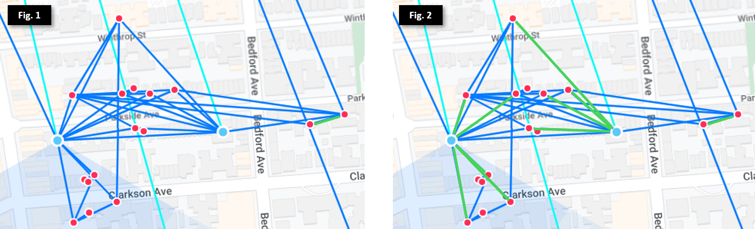
In Figure 1, we see many nodes (marked as red dots) clustered around 2 Microhubs (marked as blue dots) in Prospect Lefferts Garden, as well as multiple exit routes to the north. While most of the nodes will automatically find the best exit, there are some that may have equal costs through multiple exits. To mitigate this, we set preferred routes (via hardware like SXTs, or software with virtual wireless interfaces) on the Mesh Bridge, as illustrated by the green lines in Figure 2. This ensures each node selects its fastest and most stable route to send and receive internet traffic.
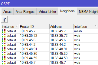
We can see this in action on the Omnitik: 10.69.45.7 is on the the "Mesh" bridge interface, meaning it incurs cost 10 to transit. All other adjacent routers are on the "WDS" bridge interface, and incur cost 100 to transit. This setup ensures the local node prefers the 4507 Microhub as its exit route, but also has backup routes in case 4507 goes offline or one of its upstream links is broken.
By implementing this architecture across all routers on the network, we now have high resiliency to outages, scalability, and minimal configuration effort.
Bridge Filters
Before we go further, its important to mention bridge filters. These are required to make OSPF work properly and also ensure members within the same building are isolated from each other. There are 3 filters applied to standard Omnitik configurations.
[admin@nycmesh-xxxx-omni] > interface bridge filter print
Flags: X - disabled, I - invalid, D - dynamic
0 chain=forward action=drop in-bridge=mesh log=no log-prefix=""
1 chain=forward action=drop in-bridge=wds
2 chain=forward action=drop in-interface=wlan2 - Filter 0 prevents devices on the Mesh Bridge from directly interfacing with each other. Disabling or deleting this filter allows traffic to move freely across devices on the Mesh Bridge without first traversing the OSPF Area and incurring the OSPF cost of 10 before moving to the next router in the exit route.
- Filter 1 functions the same as Filter 0, but applied to the WDS bridge
- Filter 2 ensures that guests connected to the open -NYC Mesh Community Wifi- SSID are isolated from each other
- Note that routers without built-in wireless access points, including "core" routers within NYC Mesh, only require Filter 0
It is critically important to ensure these filters stay enabled on each router to ensure individual routers don't "bridge" connected nodes and Hubs, leading to unintended routing paths. Further explanation and examples of bridging scenarios are covered below.
Sidebar: The case against OSPF automation and summarization
Given the scale of the problem and continued growth, we must consider an important question: why not implement automation to dynamically adjust OSPF costs based on link quality, and/or utilize summarization and redistribution to simplify planning?
As mentioned above, our network design is meant in part to balance the following three goals:
- Resiliency across a widely distributed network in a dense urban environment
- Simplicity of configuration and maintenance by a 100% volunteer team of architects, engineers, coders and enthusiasts
- Scalability for future expansion
Further, NYC Mesh has no CEO, directors, or employees, and the board intentionally does not have decision-making authority over non-financial/legal matters; as documented in the NYC Mesh Commons License, the design, planning, maintenance and support of NYC Mesh is done solely by community members and volunteers. While we do have highly-skilled volunteer network engineers, the day-to-day maintenance and monitoring of the network is done by members with varied skill levels; we generally prefer easy-to-maintain solutions over highly customized configurations requiring extensive knowledge and training.
Finally, as we primarily rely on member donations to maintain and expand the network, we generally avoid high-end enterprise-grade hardware or software requiring recurring subscription fees and support contracts to minimize operational expenses. As NYC Mesh continues to grow, we may need to adopt more robust and dynamic routing and load-balancing techniques, and will look to our community to collectively decide on the path forward.
Scaling out the Hub-and-Spoke model
This baseline architecture works great in individual neighborhoods and on relatively linear routes, but with over a thousand nodes connecting to 60+ Hubs with links crisscrossing New York City, some planning and manual intervention is required to ensure stability and speed for all connected members.
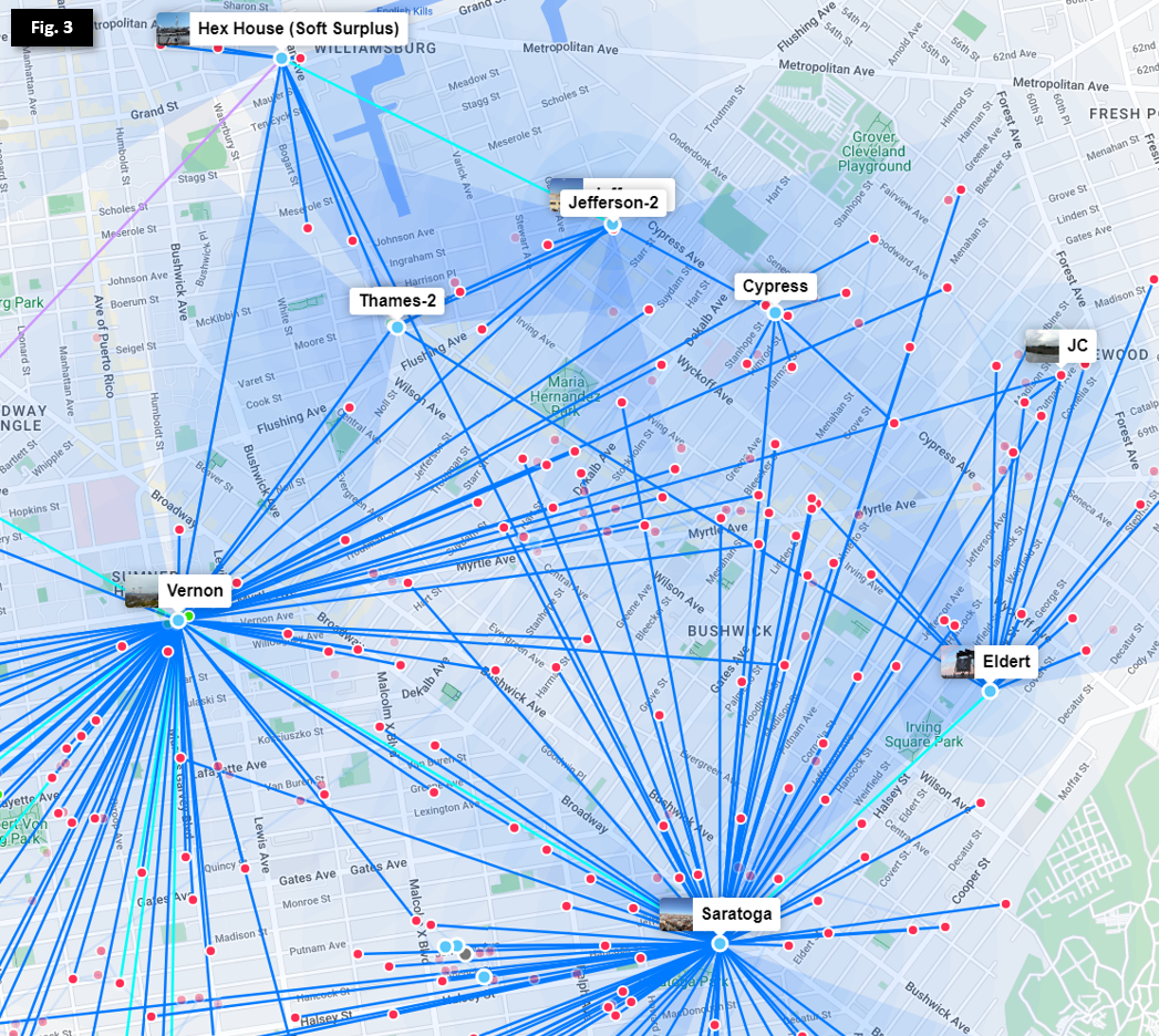
In the Bed-Stuy, Bushwick, Ridgewood, and Crown Heights neighborhoods show above in Figure 3, we have over a dozen Hubs serving hundreds of members. Efficient routing and redundancy across multiple wireless links requires further options for route cost between 10 and 100.
In efforts to minimize single points of failure in our network (hubs having only 1 exit route) and provide dedicated backup routes in cases of weather impacting high-frequency links, we deploy redundant links in a "triangle schema" so that each hub has multiple low-cost routes to exit. To see this deployed, let's remove the nodes from the above photo and focus on the Hubs.
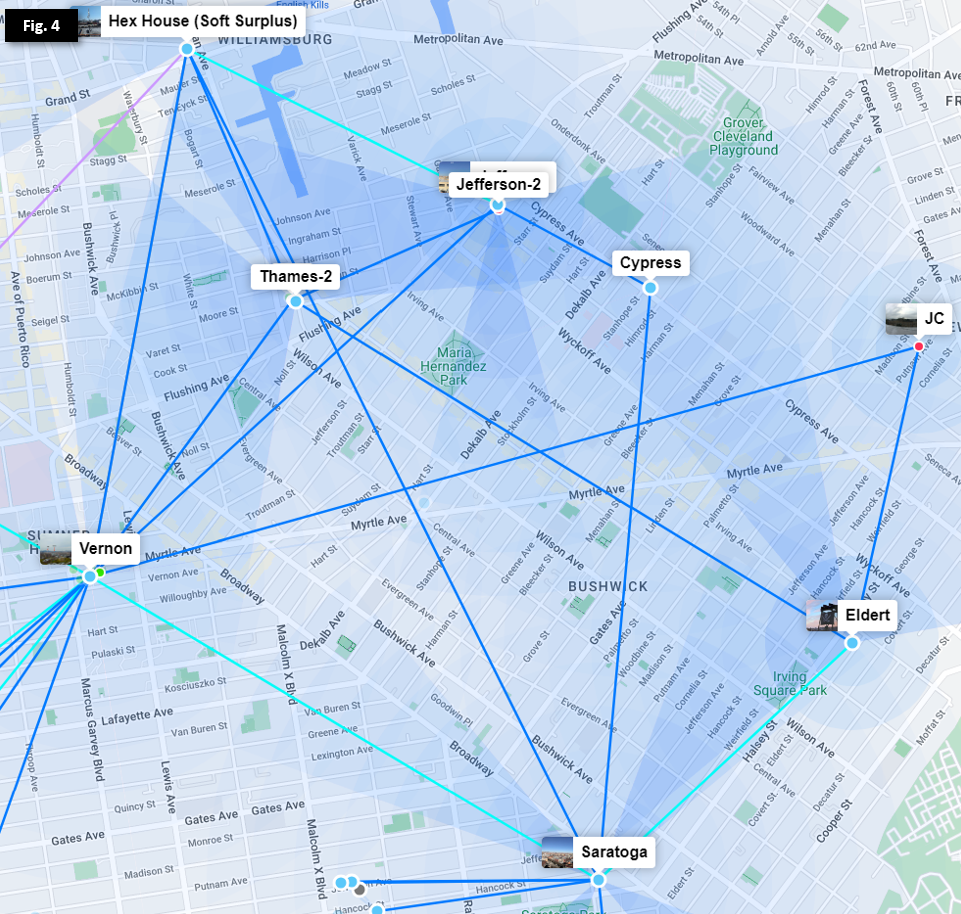
As we can see in Figure 4, most Hubs have 2 or more exit routes so that an outage of an individual link or Hub will not isolate any other Hub. Additional routes leading off Figure 4 allow multiple exits from both Vernon and Hex House, as well as other lower-capacity links through smaller Microhubs and nodes.
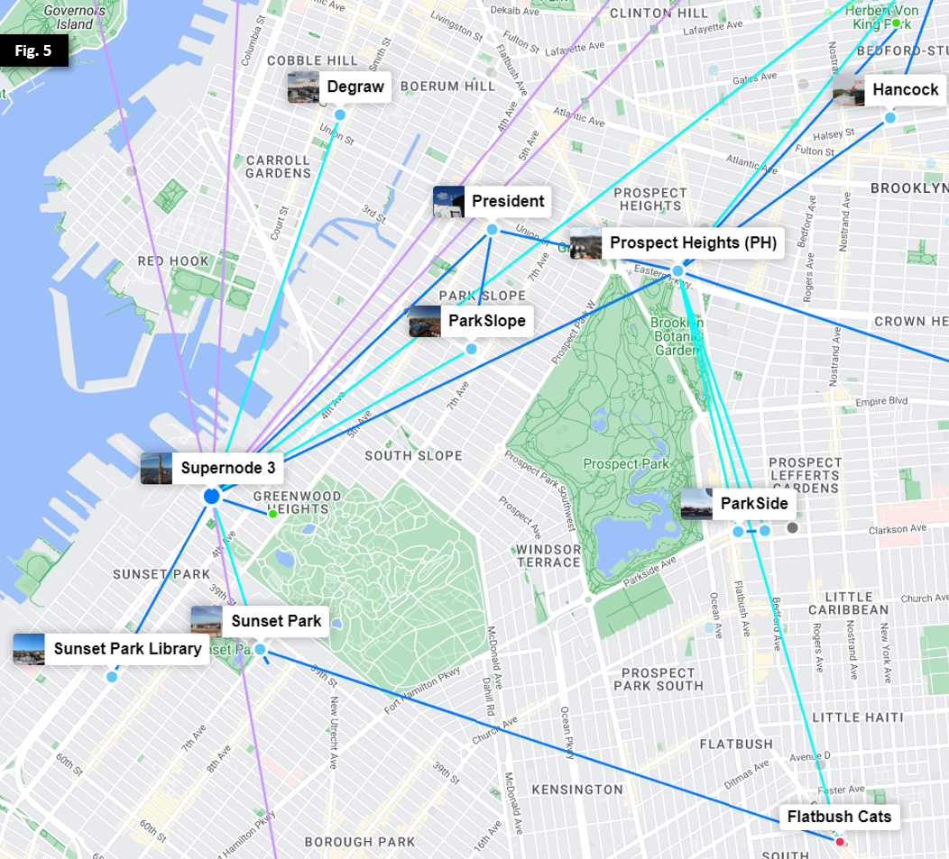
In Figure 5, we observe a similar trend as we move southwest towards Prospect Park and Supernode 3 at Industry City.
Load-balancing across varied hardware
NYC Mesh uses a broad range of purchased and donated Ubiquiti and Mikrotik hardware with varying capacity, capabilities, and rain fade resilience, and members are allowed to extend the network at will pursuant to the Network Commons License. Because our OSPF link costs are static and do not automatically increase or decrease based on link quality, limiting ourselves to just two options for link cost will quickly cause issues as the network grows. Here are just a few use cases to consider:
- Avoiding unintentional bridging of Hubs with low-capacity connections as members join and add equipment and links
- Intentional design of secondary and tertiary routes for major Hubs to mitigate rain fade and hardware failure
- Multi-antenna routes with differing performance characteristics (primarily high-capacity 60GHz links with dedicated 5GHz backup hardware)
- Minimizing impacts from misconfigured DIY and new infrastructure installations
To meet these goals, we need to set up custom link costs on backup routes as well as between high-traffic Hubs.
Example: Microhubs between Major Hubs
Our Vernon and Prospect Heights Hubs collectively carry more than 80% of NYC Mesh network traffic in Brooklyn. By design, each Hub's primary exit is through different Supernodes to the public Internet (Vernon through Supernode 10 in Manhattan, and Prospect Heights through Supernode 3 in Industry City). To allow redundancy between their exits, a dedicated 60GHz link (in teal) is deployed between the two, but Vernon and Prospect Heights also have more preferrable secondary links (illustrated further below in Figure 7). This requires the link to have a slightly higher cost (in this case, 15) so that each Hub prefers other backup routes in case of primary exit link outages.
To make matters more complicated, Microhubs in between Vernon and Prospect Heights connect to both Hubs to provide their own redundancy, as illustrated in Figure 6.
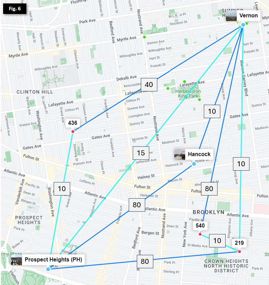 Note: nodes and sector coverage have been omitted
To ensure each Microhub prefers the fastest route and they don't bridge Vernon and Prospect Heights by having additive link costs lower than the Vernon <> Prospect Heights 60GHz link, we need to manually set the backup links with higher costs.
Reminder: before setting up secondary links, double-check that the appropriate Bridge Filters are enabled on the local router. A misconfigured or disabled Mesh Bridge Filter will result in 0-cost links between neighboring nodes and Hubs, risking major network congestion or outages.
- 436
- Primary: Prospect Heights via AF60LR PtMP (default 10 on Mesh Bridge)
- Secondary: Vernon via Litebeam 5ac PtMP (manual 40 on OSPF area)
- Hancock 3607
- Primary: Vernon via Litebeam 5ac PtP (default 10 on Mesh Bridge)
- Secondary: Prospect Heights via Litebeam LR PtMP (manual 80 on OSPF area)
- St Marks 219
- Primary: Vernon via AF60LR PtMP (default 10 on Mesh Bridge)
- Seconday: Prospect Heights via Litebeam LR PtMP (manual 80 on OSPF area)
- 540
- Primary: St Marks 219 via LHG60 PtMP (default 10 on Mesh Bridge)
- Secondary: Vernon via Litebeam 5ac PtMP (manual 80 on OSPF area)
Determining link costs
Note that there is no firm methodology or formula for calculating optimal custom link costs in this model, though backup links are generally set between 20 and 80 depending on upstream impacts. Sufficient buffer should be allocated between primary and secondary routes to allow expansion and updates with minimal changes required to upstream OSPF costs or routes.
The NYC Mesh Node Explorer tool generates live and historical mappings of nodes and link costs, allowing us to quickly determine primary exit routes and costs, as well as an outage simulator tool that is extremely helpful in validating configuration of secondary routes.
You can also determine current exit cost of any Mikrotik router running RouterOS v6 with the following command:
[admin@nycmesh-xxxx-core] > routing ospf route print where dst-address =0.0.0.0/0
# DST-ADDRESS STATE COST GATEWAY INTERFACE
0 0.0.0.0/0 ext-1 20 10.70.253.xx bond1.1010 Note: identifying information has been removed from this terminal export
When selecting a custom link cost that may bridge segments of the network, the following factors should be taken into account:
- What is the preferred exit path for the local router?
- This will normally be the link with the highest capacity (60 GHz), and will usually have default cost 10 on the Mesh Bridge to keep configuration simple
- Will the backup link connect to the same Hub as the primary, or a different one?
- When the primary and secondary/backup links connect to the same upstream Hub, it's generally safe to set the backup link to cost 20 without further impacts
- What are the current primary and secondary exit routes & costs for each upstream Hub?
- This gives us an understanding of where traffic will route along each hop of the network
- In the event of a primary link failing on an upstream Hub, will the new bridged link take priority over an existing secondary route?
- Unless the local router is intended to override an existing upstream Hub's secondary/backup route, this defines the minimum cost of the secondary link: the primary link cost + secondary link cost + exit cost after the secondary link should be greater than the existing secondary/backup exit cost at the preferred Hub. This ensures that if the upstream Hub's primary route is interrupted, it will continue to use its existing preferred backup route.
- (Optional) For the local router, is the upstream Hub's secondary exit preferred over the local router's secondary route?
- In some cases, the secondary route of the upstream Hub may have bandwidth constraints or other limitations that make the local router's backup more preferrable in the event that the upstream Hub's primary exit is interrupted. In this case, the total cost of the local backup exit route should be less than the local primary link cost + the upstream Hub's secondary exit cost, but still high enough to not cause the upstream Hub to prefer the new bridged link.
- Testing this scenario can be challenging in production environments without actively disabling preferred links; a speed test from the local router to the second-order upstream backup router is usually sufficient for planning purposes.
Planning for Outages
Ok, to summarize, we've done the following:
- Selected OSPF for simplicity and consistency across the network
- Defined default link costs for primary and WDS links across nodes and Hubs
- Set up bridge filters to ensure OSPF works properly
- Established "triangles" for higher-capacity Microhubs serving multiple members, and adjusted costs for these links to ensure we don't bridge major Hubs
- Created secondary, tertiary, and even quaternary links for Hubs and geographically-advantageous locations to ensure failover exits
To determine route costs to set on primary and backup routes, we need to understand more about the wireless hardware used in the Mesh. The table below details characteristics of the common equipment currently in use on the Mesh.
| Brand | Antenna | Band | Advertised Capacity* | Typical Capacity* | Rain Resilience | Preferred Link Distance** |
| Ubiquiti | Litebeam 5AC Gen2 Litebeam LR |
5GHz | 225 Mbps+ (40 MHz width) |
75-175 Mbps |
Extremely High | < 3.5km (PtP) < 2km (PtMP) |
| Ubiquiti | airFiber 5XHD LTU Long-Range |
5GHz | 425 Mbps+ (80MHz width) |
125-300 Mbps |
Extremely High | < 5km (PtP) < 3km (PtMP) |
| Ubiquiti | 24GHz | 750 Mbps (100MHz width) |
750 Mbps | Very High | < 5km (PtP) | |
| Ubiquiti | 60GHz | 1Gbps (1080MHz width) |
1Gbps | Medium | < 3.5km (PtP) < 2km (PtMP) |
|
| Ubiquiti | airFiber 60 XR | 60GHz | 2.7Gbps (2160MHz width) |
2.7Gbps | Low/Medium | < 5km (PtP) |
| Mikrotik | SXTsq 5AC | 5GHz | 200 Mbps+ (40 MHz width) |
75-100 Mbps | Extremely High | < 1.5km (PtP) < 500m (PtMP) |
| Mikrotik | LHG 5AC | 5GHz | 200 Mbps+ (40 MHz width) |
75-125 Mbps | Extremely High | < 3.5km (PtP) < 1.5km (PtMP) |
| Mikrotik | LHG 60 | 60GHz | 1Gbps (1080MHz width) |
300-600Mbps | Low/Medium | < 1.5km (PtP) < 500m (PtMP) |
| Siklu | Etherhaul Kilo 8010 (licensed band) |
70GHz 80GHz |
10Gbps (2160MHz width) |
10Gbps | High | < 5km (PtP) |
* Capacity listed is single-direction speed; Typical Capacity indicates observed performance in New York City
** Preferred Link Distance is a subjective estimate of maximum distance in dense urban areas before performance is significantly degraded
As we can see, decisions on route priority depend on the capacity of individual links, as well link distance (for rain resiliency) and count of hops (for latency) to an internet exit. That's a lot of factors to consider! Let's see what this looks like in the real world.
Determining Primary and Backup Costs
To see how these factors are taken into account when planning for real-world deployments, let's return to Brooklyn.
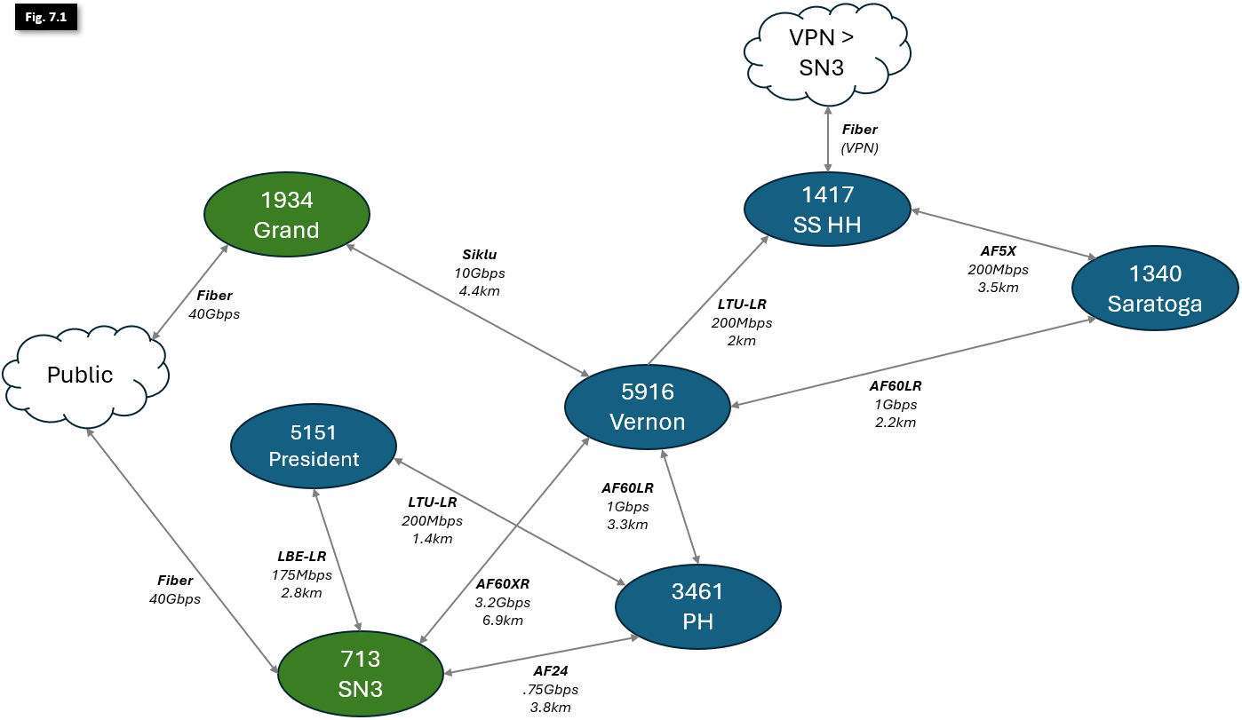 Note: some additional links and hubs omitted for clarity; listed link speeds are production single-direction actuals; distances between Hubs are not to scale
Figure 7.1 illustrates links between larger Hubs in Brooklyn, with notations indicating deployed hardware, directional link capacity and physical distance. Supernodes in green serve as Internet Exits; all other Hubs are marked in blue. As mentioned earlier in this article, all OSPF link costs are symmetrical to ensure consistent bi-directional traffic flow and ease of configuration.
Because OSPF will always prefer the lowest-cost route to an exit, its easier to work from the outside-in (i.e., starting with the Supernodes adjacent to the Internet Exits and working our way deeper into the network). To begin planning our link costs, let's start by identifying the Public Internet exits:
- Both 713 - Supernode 3, and 1934 Grand St. have 40Gbps fiber uplinks to the Public Internet. While they carry more traffic than indicated in this diagram, there is enough capacity in each of these links to comfortably carry all NYC Mesh traffic through a single Supernode if necessary. SN3 has cost 1 to exit, and Grand has cost 3.
- 1417 - Hex House (Soft Surplus) serves a number of nodes and small Microhubs, and leverages a Wireguard VPN connection over consumer fiber internet to connect to SN3. It also serves as a backup route for Vernon and Saratoga. To ensure it doesn't take too much traffic in normal network conditions, it has a total cost of 26+1=27 to exit through SN3.

With the Public Internet exits and costs identified in red in Figure 7.2, the network will operate mostly ok with default costs of 10 (noted in grey) for all other links... until we experience outages, whether from heavy rain or rare hardware failure.
To optimize the network, we'll need to make some changes to some of our primary link costs.
- Currently, all traffic will exit through SN3. We want to change Vernon, which supports hundreds of members and dozens of Hubs, to prioritize the SIklu link over the AF60XR, increasing rain resiliency and capacity. To accomplish this, we'll need to make 2 changes:
- Decrease the Siklu link to cost 8, for a total exit cost of 8+3=11 via Grand.
- Increase the AF60XR link cost to 11, for a total backup exit cost of 11+1=12 via SN3.
- We can leave the Prospect Heights and President links as-is; these single-hop links have more than enough bandwidth to serve their local and upstream members. Both have a total exit cost of 10+1=11.
With these changes in place, Vernon now prioritizes traffic correctly over its highest-capacity link, and has a dedicated high-capacity secondary failover link in case of hardware failure or a Grand outage. Additionally, Saratoga will now also follow Vernon's exit to Grand.

We now have traffic moving more efficiently, and can operate with plenty of overhead for traffic spikes and growth. However, if we experience heavy rainfall or suffer outages, we may still have problems. We'd also like to make sure we don't have to redesign the entire OSPF schema from the ground up very time a new Hub is stood up. We'll work to address that now:
- To prefer higher-capacity links in our secondary routes, let's change the following:
- The Saratoga AF5X link cost to Soft Surplus can be increased to 20, and the PH AF60LR link to Vernon can be increased to 15 to leave some room for growth.
- To ensure PH prefers Vernon as its secondary exit, the President <> PH link can be increased to 30 and will continue to be the secondary exit for President.
- Because Saratoga and Vernon have many Microhubs between them that risk bridging these two larger Hubs (as illustrated in Figure 4), we'll decrease that link cost to 9 to mitigate this risk.
- Since we increased the Saratoga <> Soft Surplus secondary link cost, we'll also want to increase the cost of the Vernon LTU-LR link to Soft Surplus so that Saratoga and Vernon will balance their traffic across their dedicated lower-capacity Soft Surplus links if Vernon gets isolated from both Supernodes.
- Additionally, Soft Surplus and its small number of connected nodes and Microhubs should use its weather-proof fiber VPN link as their primary exit instead of traversing less resilient wireless links.
- To address both needs, we'll increase the Vernon <> Soft Surplus LTU-LR link cost to 28.
Let's see how our network looks in Figure 7.4 now that we've put these changes in place.
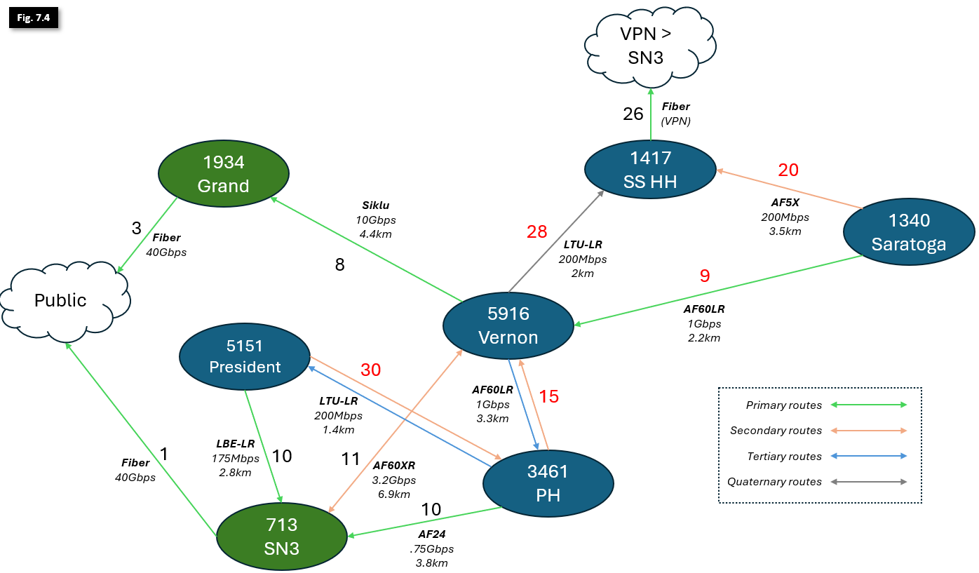
We now have efficient routing in place with high-resiliency backups for rain as well as high-capacity backups for hardware failures and outages!
If you've made it this far, you should have a good understanding of how to safely manage routes and costs on the Mesh, and be able to plan for new nodes and Hubs armed with a better understanding of traffic flow across the network.
To learn how to configure OSPF routes on our Mikrotik routers, see the OSPF Configuration Guide to get started.
Appendix: Brooklyn Hub OSPF Costs
Note: the routing details in this document are accurate as of April 11th, 2024. Before making production routing changes, check the NYC Mesh Node Explorer tool and discuss in our Slack #architecture channel.
1340 - Saratoga
- This hub serves a large amount of nodes and Microhubs, carrying 1-400Mbps traffic at any given moment.
- Its primary exit is through a 1.95Gbps AF60LR to Vernon, with total exit cost of 9+8+3=20 via Grand.
- This 2.2km 60GHz link occasionally experiences interruptions in heavy rain and snow.
- Its secondary exit is a 200Mbps AF5X to Hex House, with a total exit cost of 20+26+1=47.
- Although this 3.5km 5GHz link does not have enough capacity to consistently carry all local traffic, it is extremely resilient to weather impacts, making it preferrable over a high-frequency, high-capacity antenna.
3461 - Prospect Heights:
- Similar to Saratoga, this hub serves a large amount of nodes, Microhubs and Hubs, carrying 2-500Mbps traffic at any given moment
- Its primary exit is through a 750Mbps AF24 to SN3, with total exit cost of 10+1=11 via SN3.
- While this 3.8km 24GHz link has lower capacity than a similar 60GHz model, it has much better weather resiliency and experiences only a few minutes of downtime per year
- Its secondary exit is a 1.95Gbps AF60LR to Vernon, with total exit cost of 15+8+3=26 via Grand.
- This 3.3km 60GHz link is less resilient to weather, and is intended only as a failover in case the AF24 link goes down due to hardware malfunction or SN3 outage.
- Its tertiary exit is a 200Mbps LTU-LR to President - 5151, with total exit cost of 30+10+1=41 via SN3.
- Similar to Saratoga's secondary route, this 1.4km 5GHz link is extremely resilient to weather impacts.
5151- President
- While this hub serves 15-20 members, normally only carrying ~25-100Mbps in traffic, its location and height make it worthwhile to include in our analysis as it serves as a backup to multiple Hubs.
- Its primary exit is through a 175Mbps Litebeam LR to SN3, with total exit cost of 10+1=11.
- This 2.8km 5GHz link is extremely resilient to weather impacts, and given the smaller footprint and bandwidth requirements of this Hub, is preferred over 60GHz hardware.
- Its secondary exit is a 200Mbps LTU-LR to Prospect Heights, with total exit cost of 30+10+1=41 via SN3.
- It also has a tertiary 5GHz 100Mbps exit through 1635 - Park Slope (not shown in this diagram), and is secondary exit for that Hub.
5916 - Vernon
- The Vernon Hub is our largest and most heavily trafficked in Brooklyn, serving a very large number of nodes, dozens of Microhubs, and many Hubs as a primary exit to the Public Internet. Its location and height advantage over nearby neighborhoods make it a critical backbone of the Mesh. It typically carries 600-1200Mbps of traffic.
- Its primary exit is through a 10Gbps SIklu EtherHaul to Grand, with total exit cost of 8+3=11.
- This 4.4km licensed 70GHz link is fairly resilient to rain and snow, but does occasionally experience service degradation and interruptions in heavy precipitation.
- Its secondary exit is through a 3.2Gbps AF60XR link to SN3, with total exit cost of 11+1=12.
- Similar to Prospect Heights' secondary, this 6.9km 60GHz link, the longest in NYC Mesh production use, has poor weather resilience, and is intended only as a failover in case the Siklu link goes down due to hardware malfunction or Grand outage.
- Its tertiary exit is the 1.95Gbps AF60LR to Prospect Heights, with total exit cost of 15+10+1=26 via SN3.
- Similar to the secondary exit, this 60GHz 3.3km link is only intended as a bidirectional failover in case of multiple hardware failures and/or Supernode outages.
- Its quaternary exit is a 200Mbps LTU-LR to Hex House, with total exit cost of 28+26+1=55 via SN3.
- Although this 2km 5GHz link does not have enough capacity to consistently carry all local traffic, similar to Saratoga's secondary link, it is extremely resilient to weather impacts and provides an exit in cases of especially severe weather interrupting all other higher-capacity links.
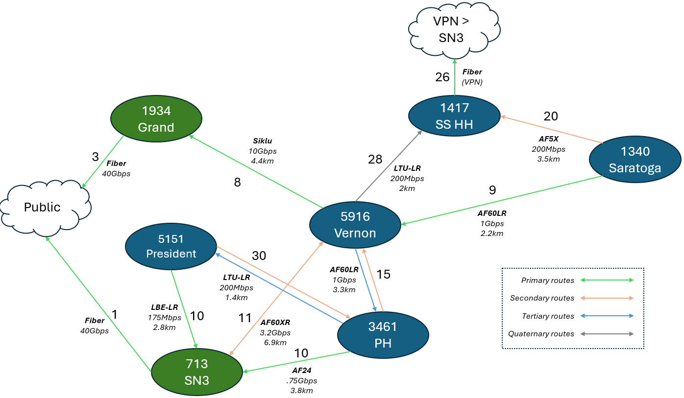
Rules and Standards
As OSPF has some challenges in deployment outside of a datacenter environment, we will need to all adhere to some rules to prevent from encountering a routing problem. OSPF, unlike BGP or other protocols, may/will refuse to connect to a peer which has different parameters set and can be a source of confusion. Please follow these rules unless there is a good reason not to:
- General
- All OSPF usage will be on area
0.0.0.0( backbone area ) - Set Router ID to the 10-69-net address of the Node
- All OSPF timers will be set to ( this is typically default ):
- Link Cost 10
- Retransmit Interval 5
- Transmit Delay 1
- Hello Interval 10
- Dead Router Interval 40
- All OSPF usage will be on area
- Interfaces should be in PtMP mode (not broadcast)
- OSPF "networks" should only be the 10-69-net, unless there is a special case
- Redistribute Default Route should be
never, unless you are distributing a default route- If you are redistributing a default route, do so
as type 1 - Check with the rest of the network what the correct metric should be
- If you are redistributing a default route, do so
- Redistribute user networks via Redistribute Connected
as type 1 - Mikrotik Only: Filter VPN point-to-point /32 links. They cause trouble.
- For RouterOS 6, do not also run BGP on the standard mesh bridge, unless there is a special case; this has been known to cause problems in the past
- For RouterOS 7, BGP is working on the mesh bridge in a few locations as of July 2024; as ROS7 is not widely utilized within NYC Mesh yet, thorough testing and monitoring should be done for ROS7 routers
OSPF Configuration Guide
This guide contains in-depth parameters on Layer 2 and 3 configurations. This guide is not meant to be a comprehensive guide on overall networking, but an extension of existing concepts to solve Mesh-specific problems.
It is encouraged that you familiarize yourself with the NYC Mesh OSPF Routing Methodology to better understand the concepts and techniques in this page prior to putting these methods into practice.
What is the "Mesh bridge"?
On the Mesh, almost all routers have a "mesh bridge", which is an isolated, virtualized switch that connects home/apartment routers and radios together. All of the wireless radios on the NYC Mesh network are configured to operate in "bridge" mode, which means that the routers themselves are responsible for sending and routing packets to their neighbors which will be visible through the connected radios. As detailed in our routing methodology, this bridge is set with a standardized cost of 10 across the network to facilitate simple deployment of new equipment and ease-of-use for the volunteers that support and maintain it.
To see what OSPF interfaces are configured on a Mikrotik router on ROS6, use the routing ospf interface print command.
[admin@nycmesh-8300-omni] > routing ospf interface print
Flags: X - disabled, I - inactive, D - dynamic, P - passive
# INTERFACE COST PRIORITY NETWORK-TYPE AUTHENTICATION AUTHENTICATION-KEY
0 mesh 10 1 ptmp none
1 wds 100 1 ptmp none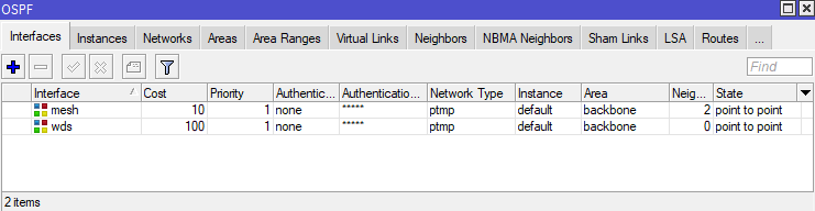
Adjacent routers in an OSPF area see each other as "neighbors", and each router is aware of all other routers in its area. On Mikrotik routers, you can see the OSPF neighbors by using the routing ospf neighbor print command.
[admin@nycmesh-8300-omni] > routing ospf neighbor print
0 instance=default router-id=10.69.83.1 address=10.69.83.1 interface=mesh
priority=1 dr-address=0.0.0.0 backup-dr-address=0.0.0.0 state="Full"
state-changes=4 ls-retransmits=0 ls-requests=0 db-summaries=0
adjacency=4h39m31s
1 instance=default router-id=10.69.5.44 address=10.69.5.44 interface=mesh
priority=1 dr-address=0.0.0.0 backup-dr-address=0.0.0.0 state="Full"
state-changes=5 ls-retransmits=0 ls-requests=0 db-summaries=0
adjacency=4h39m38s
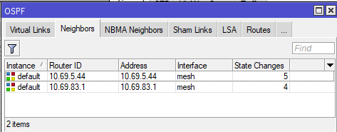
In the above example, we see that this router has two neighbors, 10.69.5.44 and 10.69.83.1, and both are on the "mesh" interface which has a cost of 10.
Why would you need a non-standard OSPF interface?
Sometimes the need will arise that a particular link should have a different cost than the mesh bridge standard, such as:
- Links between hubs to dictate preferred routes based on wireless link speed, quality, and rain resiliency
- Forcing a preferred route at a node over a backup route
- Ensuring new nodes and hubs with multiple links do not inadvertently become primary exit routes for higher-capacity hubs
- Utilizing BFD for faster failover on links with poor rain performance
The solution to this is to create a new dedicated OSPF interface (which is not on the mesh bridge) between two routers with a point-to-point address space, and a non-standard cost.
Considerations for Configuration
The implementation of an OSPF interface depends on two factors:
- If the link is Point-to-Point (two radios that only connect to each other, or a wired link), or Point-to-Multipoint (one radio connected to an access point that serves one or more other radios)
- Whether there is a switch between the router and the radio, and if it is managed or unmanaged
The following table shows the most common link types and their requirements for OSPF configuration. Note that each end of a link may have different characteristics, and therefore different requirements. Some routers and radios support VLAN tagging on egress; for the purposes of simplicity and conformity to NYC Mesh standards, VLAN interfaces should be used as follows
| Link Type | Connection to Router | VLAN Interface Required | Switch port egress |
| PtP | Direct | No | N/A |
| PtP | Through managed switch | Yes* | Untagged |
| PtMP |
Direct or through managed switch | Yes (both ends) | Tagged |
| Any | Through unmanaged (dumb) switch | Yes (both ends) | N/A (Tagged) |
Sidebar: nuances of VLAN configurations with Mikrotik and Ubiquiti Hardware
Before describing implementation steps, it's important to understand how VLANs work on switch ports; in all PtMP links, or if either end of the link has a switch between the radio and router (extremely common at NYC Mesh hubs), you will need to create VLAN interfaces on the router and instruct the switch where to send the VLAN-tagged traffic.
The first concept to understand is Ingress vs Egress Traffic
- Ingress traffic is traffic entering a physical or virtual port on a device, which is then passed to other interfaces or bridges on the local device
- Egress traffic is traffic exiting a physical or virtual port on the local device to a another connected device
- For the purposes of routing and switching tables, an ingress port is the port that traffic enters the device through, and the egress port is the port that it exits through
The second concept is a VLAN interface on Mikrotik devices, which is a virtual interface associated with a physical port that "listens for" tagged traffic through the physical port only with the specified VLAN ID, and automatically untags that traffic before passing it onto the bridge or OSPF instance. This also works in reverse; untagged traffic on the bridge or OSPF Interface can "enter" the vlan interface and is tagged before egress out the physical port.
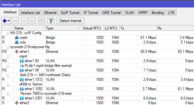
Multiple VLAN Interfaces on a single physical router port
The third concept is VLAN behavior on switch ports. On a managed switch, generally you must define what ports are allowed to pass traffic with specific VLAN tags in the VLAN table, but you also have the ability to add, modify, and remove tags on traffic entering and exiting the switch port, which will be key for configuration later in this guide. Mikrotik and Ubiquiti use similar terminology on their switches:
- for Mikrotik switches, bridge vlan-filtering=yes must be enabled on the bridge otherwise tagged traffic will be able to ingress/egress through any port on the bridge
- Switch ports set as Tagged for a VLAN are allowed to pass both ingress and egress tagged traffic with the specified VLAN, but do not modify the tag. These are commonly used for Trunk ports.
- Switch ports set as Untagged for a VLAN will accept the tagged ingress traffic from the switch chip and strip the specified VLAN ID on egress.
- On Ubiquiti Edgepoint S16 switches, untagged ingress traffic on the port will be automatically tagged with the VLAN ID specified
- On Mikrotik devices, untagged ingress is usually not automatically tagged; this can be accomplished with the "PVID" value on the bridge port vlan setting
- Note that you must specify at least 2 ports per VLAN, otherwise the traffic will be dropped by the switch
[admin@nycmesh-219-netpower16p] /interface bridge vlan> print
Flags: X - disabled, D - dynamic
# BRIDGE VLAN-IDS CURRENT-TAGGED CURRENT-UNTAGGED
0 ;;; lbelr to PH
bridge 1072 ether1
ether15
1 bridge 99 ether1 sfp-sfpplus1
2 ;;; Revere 7985 (lbe)
bridge 2301 ether1
ether14
3 ;;; mgmt
bridge 50 ether1
ether15
ether13
4 ;;; af60 to Vernon
bridge 1092 ether1
ether13 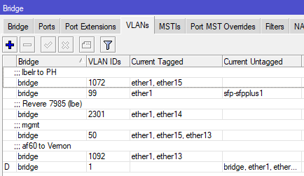
Bridge VLAN table on a Mikrotik Netpower 16P
Implementation scenarios with directly-connected antennas
The following section details the configuration steps for the scenarios listed in the table above. While this will not cover every scenario you may find, it should give you the knowledge needed to create links of varying complexity.
Important Notes: Making changes to default OSPF costs can have unintended effects, up to and including network-wide outages, and frequently requires modifying Hub configurations. Testing and learning should not be done in production environments. Before making changes to NYC Mesh routing configurations, discuss in our Slack #architecture channel and/or applicable hub channel and check the NYC Mesh Node Explorer tool for current routing information.
Before setting up secondary links, double-check that the appropriate Bridge Filters are enabled on the local router. A misconfigured or disabled Mesh Bridge Filter may result in 0-cost links between neighboring nodes and Hubs, risking major network congestion or outages.
When implementing changes in production, be mindful of order of operations and availability of backup routes; removing a remote interface from the mesh bridge will cause the link to drop and you may lose remote access to the router if there is not another OSPF neighbor visible to the router
At a high level, this configuration is simpler than it sounds.
- Reserve a point-to-point address space (/31 for Mikrotik, /30 for Juniper) for the two routers to connect
- If the data will traverse through a switch or an Access Point/PtMP antenna on either end, create VLAN interfaces on both routers for tagged traffic to traverse the link
- On the non-AP side, create a second VLAN interface for management access to the radio, added to the mesh bridge, and set the radio's management VLAN to match
- Add the IP addresses from the point-to-point address space to the interfaces on both ends
- Add the physical (for PtP with no switches) or VLAN interfaces as OSPF interfaces on the routers as "PTMP" network type with bfd enabled
- Add the point-to-point OSPF address space to the backbone
- On the non-AP side(s), remove/disable the physical interface from the Mesh bridge so data can only traverse through the new OSPF interface
- If data will traverse through a switch, update the switch vlan table to allow tagged traffic to pass
This diagram shows how this would look logically for a Microhub on the left to connect to two different Hubs with separate exits; this grants automatic failover for Microhub A in the event that the primary link, or Hub B / Supernode X goes down.
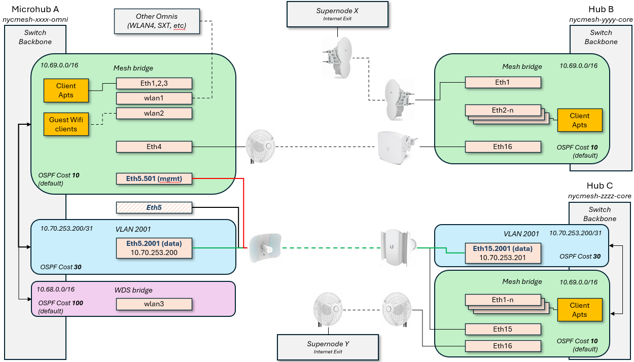
Scenario 1: Point to Point with directly-attached antennas
Router A > untagged > Antenna A <> Antenna B < untagged < Router B
This is the simplest configuration, as each end of the link has an antenna (or hardwire) plugged directly into the routers on each end. Because all traffic through the link should be on the new interface, we do not need to create any VLAN interfaces; the physical port itself can be removed from the Mesh bridge and added as a standalone OSPF interface with adjusted cost.
- If performing this on a remote site, ensure the link being adjusted is not a single point of failure before proceeding
- Reserve an unused /31 IP range to be used for the OSPF network (ask in the #architecture channel for access to the IP ranges sheet for more information on this)
- For this example, I will use 10.70.253.200/31
- If one or both of the routers is running Juniper OS, you will need a /30 reservation
- On each router, add the reserved IPs and network to the appropriate interfaces
RouterA: /ip address add address=10.70.253.200 network=10.70.253.201 interface=ether1 RouterB: /ip address add address=10.70.253.201 network=10.70.253.200 interface=ether5You can verify they were added correctly with /ip address print
[admin@nycmesh-8300-omni] > ip address print Flags: X - disabled, I - invalid, D - dynamic # ADDRESS NETWORK INTERFACE 0 10.104.27.1/26 10.104.27.0 mesh 1 10.69.83.0/16 10.69.0.0 mesh 2 10.68.83.0/16 10.68.0.0 wds 3 10.70.253.200/32 10.70.253.201 ether1 - On each router, add the physical port as an OSPF interface with the correct cost, set for "PTMP", and enable BFD. For this example, I will use cost 9.
You can verify they were added correctly with /routing ospf interface printRouterA: /routing ospf interface add cost=9 interface=ether1 network-type=ptmp use-bfd=yes RouterB: /routing ospf interface add cost=9 interface=ether5 network-type=ptmp use-bfd=yes
[admin@nycmesh-8300-omni] > routing ospf interface print Flags: X - disabled, I - inactive, D - dynamic, P - passive # INTERFACE COST PRIORITY NETWORK-TYPE AUTHENTICATION AUTHENTICATION-KEY 0 mesh 10 1 ptmp none 1 wds 100 1 ptmp none 2 ether1 9 1 ptmp none - On each router, add the OSPF Network so the OSPF interface is routable. Note that this command is identical on both ends.
You can verify they were added correctly with /routing ospf network printRouterA: /routing ospf network add area=backbone network=10.70.253.200/31 RouterB: /routing ospf network add area=backbone network=10.70.253.200/31
[admin@nycmesh-8300-omni] > routing ospf network print Flags: X - disabled, I - invalid # NETWORK AREA 0 10.69.0.0/16 backbone 1 10.68.0.0/16 backbone 2 10.70.253.200/31 backbone - On each router, remove the PtP interface from the Mesh Bridge. This should be done on the remote router first, as you will lose connectivity to the remote device until the local device is updated and the neighbors are re-established
You can verify this is set correctly with /interface bridge port print. For 0 - ether1, the "X" indicates the port is disabledRouter B: /interface bridge port set 4 disabled=yes Router A: /interface bridge port set 0 disabled=yes
[admin@nycmesh-8300-omni] > interface bridge port print; Flags: X - disabled, I - inactive, D - dynamic, H - hw-offload # INTERFACE BRIDGE HW PVID PR PATH-COST INTERNA... HORIZON 0 XI ether1 mesh 1 0x 10 10 none 1 I ether2 mesh no 1 0x 10 10 none 2 I ether3 mesh no 1 0x 10 10 none 3 I ether4 mesh no 1 0x 10 10 none 4 I ether5 mesh no 1 0x 10 10 none 5 I wlan1 mesh 1 0x 10 10 none 6 I wlan2 mesh 1 0x 10 10 none 7 I wlan4 mesh 1 0x 10 10 none 8 I wlan3 wds 1 0x 10 10 none 9 dynamic wds yes 1 0x 100 100 none - Once the bridge ports are disabled on both ends, the OSPF link will activate and establish adjacency; you can validate this on either router with /routing ospf neighbor print
[admin@nycmesh-8300-omni] > /routing ospf neighbor print 0 instance=default router-id=10.69.83.1 address=10.70.253.201 interface=ether1 priority=1 dr-address=0.0.0.0 backup-dr-address=0.0.0.0 state="Full" state-changes=9 ls-retransmits=0 ls-requests=0 db-summaries=0 adjacency=6m30s
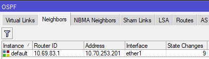
Now we have established a 9-cost OSPF link between the two routers! This cost can be changed at will as the network topology changes in the future.
Scenario 2: Point to Multipoint with directly attached antennas
Router A > tagged > Antenna A <> Access Point B < tagged < Router B
This set up is more complicated, because we need to be able to establish a new OSPF session between Router A and RouterB without impacting its existing mesh interface neighbors that are also connected to Access Point B. Unlike the previous example, we need a way for RouterB to know to only send RouterA's traffic to the new OSPF interface, but leave all the other traffic on the default mesh interface.
This is where VLAN interfaces come into play - tagging the traffic with a VLAN ID will allow the traffic to be routed correctly. In this case, we will only be removing the physical port from the mesh bridge on Router A, detailed below
- Reserve an unused /31 IP range and VLAN ID to be used for the OSPF network (ask in the #architecture channel for access to the IP ranges sheet for more information on this)
- For this example, I will again use 10.70.253.200/31, and VLAN ID 3001
- For this example, I will again use 10.70.253.200/31, and VLAN ID 3001
- To ensure we don't lose access to Antenna A's management portal later, create a VLAN interface on RouterA for management and add it to the mesh bridge; this can be any VLAN ID, as long as the same ID isn't being used for management on the other end of the link (because we don't want the two routers to see each other on this vlan). We normally use a X01 VLAN ID related to the physical port. In our case, because the antenna is on ether1, I will use 101.
RouterA: /interface vlan add interface=ether1 name=ether1.101 vlan-id=101 RouterA: /interface bridge port add bridge=mesh interface=ether1.101
- On the antenna, set the Management VLAN ID to match the VLAN you just added and save; you should retain connectivity.

- On each router, create a vlan interface for VLAN 3001 on the physical port the antennas are connected to. We need to use the same VLAN on both ends whenever we traverse through an Access Point to keep this traffic identifiable on both ends of the link. Note that you will not add these interfaces to the mesh bridge.
RouterA: /interface vlan add interface=ether1 name=ether1.3001 vlan-id=3001 RouterB: /interface vlan add interface=ether5 name=ether1.3001 vlan-id=3001
- On each router, add the reserved IPs and network to the appropriate VLAN 3001 interfaces
RouterA: /ip address add address=10.70.253.200 network=10.70.253.201 interface=ether1.3001 RouterB: /ip address add address=10.70.253.201 network=10.70.253.200 interface=ether5.3001You can verify they were added correctly with /ip address print
On each router, add the vlan interface as an OSPF interface with the correct cost, set for "PTMP", and enable BFD. For this example, I will again use cost 9.[admin@nycmesh-8300-omni] > ip address print Flags: X - disabled, I - invalid, D - dynamic # ADDRESS NETWORK INTERFACE 0 10.104.27.1/26 10.104.27.0 mesh 1 10.69.83.0/16 10.69.0.0 mesh 2 10.68.83.0/16 10.68.0.0 wds 3 10.70.253.200/32 10.70.253.201 ether1.3001
You can verify they were added correctly with /routing ospf interface printRouterA: /routing ospf interface add cost=9 interface=ether1.3001 network-type=ptmp use-bfd=yes RouterB: /routing ospf interface add cost=9 interface=ether5.3001 network-type=ptmp use-bfd=yes
[admin@nycmesh-8300-omni] > routing ospf interface print Flags: X - disabled, I - inactive, D - dynamic, P - passive # INTERFACE COST PRIORITY NETWORK-TYPE AUTHENTICATION AUTHENTICATION-KEY 0 mesh 10 1 ptmp none 1 wds 100 1 ptmp none 2 ether1.3001 9 1 ptmp none - On each router, add the OSPF Network so the OSPF interface is routable.
You can verify they were added correctly with /routing ospf network printRouterA: /routing ospf network add area=backbone network=10.70.253.200/31 RouterB: /routing ospf network add area=backbone network=10.70.253.200/31
[admin@nycmesh-8300-omni] > routing ospf network print Flags: X - disabled, I - invalid # NETWORK AREA 0 10.69.0.0/16 backbone 1 10.68.0.0/16 backbone 2 10.70.253.200/31 backbone - At this point, the two routers should establish adjacency on the VLAN interfaces, and if the cost is <10, then traffic will prefer that route.
[admin@nycmesh-8300-omni] > /routing ospf neighbor print 0 instance=default router-id=10.69.83.1 address=10.70.253.201 interface=ether1.3001 priority=1 dr-address=0.0.0.0 backup-dr-address=0.0.0.0 state="Full" state-changes=4 ls-retransmits=0 ls-requests=0 db-summaries=0 adjacency=47s 1 instance=default router-id=10.69.83.1 address=10.69.83.1 interface=mesh priority=1 dr-address=0.0.0.0 backup-dr-address=0.0.0.0 state="Full" state-changes=4 ls-retransmits=0 ls-requests=0 db-summaries=0 adjacency=11m26s
- The last step is to remove RouterA's physical port from the mesh bridge, so that traffic can only route through the new VLAN interface you have created. Note that we do not do this step on RouterB, because we want the untagged traffic from other connected antennas to continue to enter the mesh bridge.
Now, OSPF Neighbors will only show the VLAN interface and you are done!Router A: /interface bridge port set 0 disabled=yes

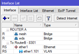
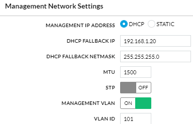
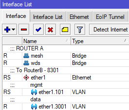
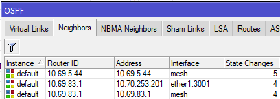
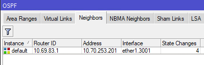
Implementation scenarios where a switch exists between the antennas and routers
Scenario 3: Point to Multipoint with a switch at one or both ends
Router A > tagged > Antenna A <> Access Point B < tagged < Switch B < tagged < Router B
This is one of the most common scenarios you'll encounter in the NYC Mesh network; many multi-member nodes and smaller hubs have a high-capacity 60Ghz radio with a backup 5Ghz radio to the same or a different hub for failover in heavy rain. This scenario is almost identical to Scenario 2, with one important caveat: we have to configure the switch to pass the VLAN traffic to the appropriate switch port.
- Reserve an unused /31 IP range and VLAN ID to be used for the OSPF network (ask in the #architecture channel for access to the IP ranges sheet for more information on this)
- For this example, I will again use 10.70.253.200/31, and VLAN ID 3001
- For this example, I will again use 10.70.253.200/31, and VLAN ID 3001
- To ensure we don't lose access to Antenna A's management portal later, create a VLAN interface on RouterA for management and add it to the mesh bridge; this can be any VLAN ID, as long as the same ID isn't being used for management on the other end of the link. We normally use a X01 VLAN ID related to the physical port. In our case, because the antenna is on ether1, I will use 101.
RouterA: /interface vlan add interface=ether1 name=ether1.101 vlan-id=101 RouterA: /interface bridge port add bridge=mesh interface=ether1.101 - On Antenna A, set the Management VLAN ID to match the VLAN you just added and save; you should retain connectivity.
- On each router, create a vlan interface for VLAN 3001 on the physical port the antenna/switch is connected to. For this example, let's assume that RouterB uses the bond1 interface to connect to the Switch.
RouterA: /interface vlan add interface=ether1 name=ether1.3001 vlan-id=3001 RouterB: /interface vlan add interface=bond1 name=bond1.3001 vlan-id=3001
Note: If there is a bonded/LAG interface (where multiple SFP/ethernet ports are used for uplink), then you should put the vlan interface on the bonded interface - On each router, add the reserved IPs and network to the appropriate VLAN 3001 interfaces
RouterA: /ip address add address=10.70.253.200 network=10.70.253.201 interface=ether1.3001 RouterB: /ip address add address=10.70.253.201 network=10.70.253.200 interface=bond1.3001 - On each router, add the vlan interface as an OSPF interface with the correct cost, set for "PTMP", and enable BFD. For this example, I will again use cost 9.
RouterA: /routing ospf interface add cost=9 interface=ether1.3001 network-type=ptmp use-bfd=yes RouterB: /routing ospf interface add cost=9 interface=bond1.3001 network-type=ptmp use-bfd=yes - On each router, add the OSPF Network so the OSPF interface is routable.
RouterA: /routing ospf network add area=backbone network=10.70.253.200/31 RouterB: /routing ospf network add area=backbone network=10.70.253.200/31 - Here is where we diverge from Scenario 2: we must configure Switch B to pass the tagged traffic to the correct egress port. In this example, let's assume the trunk port to the router is also bond1, and the Access Point is on ether8 on a Mikrotik switch
If not already enabled, we also need to enable vlan-filtering on the SwitchB bridge and ether8.SwitchB: /interface bridge vlan add bridge=bridge tagged=ether8,bond1 vlan-ids=3001
If the switch is a Ubiquiti S16, you would add the VLAN ID and set the trunk and AP ports as Tagged for VLAN 3001, and exclude all other portsSwitchB: /interface bridge set 0 vlan-filtering=yes ether-type=0x8100 pvid=1 frame-types=admit-all SwitchB: /interface bridge port set 7 vlan-filtering=yes ingress-filtering=yes

Note: If there is also a switch between Router A and Antenna A, repeat step 8 on Switch A to allow tagged traffic to pass to the appropriate port
- The two routers should establish adjacency on the VLAN interfaces, and if the cost is <10, then traffic will prefer that route.
[admin@nycmesh-8300-omni] > /routing ospf neighbor print 0 instance=default router-id=10.69.83.1 address=10.70.253.201 interface=ether1.3001 priority=1 dr-address=0.0.0.0 backup-dr-address=0.0.0.0 state="Full" state-changes=4 ls-retransmits=0 ls-requests=0 db-summaries=0 adjacency=47s 1 instance=default router-id=10.69.83.1 address=10.69.83.1 interface=mesh priority=1 dr-address=0.0.0.0 backup-dr-address=0.0.0.0 state="Full" state-changes=4 ls-retransmits=0 ls-requests=0 db-summaries=0 adjacency=11m26s - The last step is to remove RouterA's physical port from the mesh bridge, so that traffic can only route through the new VLAN interface you have created. Note that we do not do this step on RouterB, because we want the untagged traffic from other connected antennas to continue to enter the mesh bridge.
Router A: /interface bridge port set 0 disabled=yes - Now, OSPF Neighbors will only show the VLAN interface and you are done!
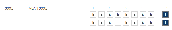
Scenario 4: Point to Point with switches on one end
Router A > untagged > Antenna A <> Antenna B < untagged < Switch B < tagged < Router B
This is another common scenarios you'll encounter in the NYC Mesh network, where two hubs connect to each other with dedicated antennas. Similar to Scenario 2, we have to configure the switch to pass the VLAN traffic to the appropriate switch port; but on router A, we do not need a VLAN since the antenna is plugged directly into Router A.
- Reserve an unused /31 IP range to be used for the OSPF network (ask in the #architecture channel for access to the IP ranges sheet for more information on this)
- For this example, I will again use 10.70.253.200/31
- For this example, I will again use 10.70.253.200/31
- Create a vlan interface with a VLAN of your choice on the physical port the switch is connected to; if there are switches on both ends of the link, do the same on the other end (the VLANs do not have to be the same, but can be if you choose). For this example, let's assume that RouterB uses the bond1 interface to connect to the Switch, and we will use VLAN 2101.
RouterB: /interface vlan add interface=bond1 name=bond1.2101 vlan-id=2101
Note: If there is a bonded/LAG interface (where multiple SFP/ethernet ports are used for uplink), then you should put the vlan interface on the bonded interface - On each router, add the reserved IPs and network to the appropriate physical or virtual interfaces. Because RouterA connects directly to AntennaA, we add the address to ether1; for RouterB, we use the bond1.2101 interface we just created in step 2.
RouterA: /ip address add address=10.70.253.200 network=10.70.253.201 interface=ether1 RouterB: /ip address add address=10.70.253.201 network=10.70.253.200 interface=bond1.2101 - On each router, add the applicable interface as an OSPF interface with the correct cost, set for "PTMP", and enable BFD. For this example, I will again use cost 9.
RouterA: /routing ospf interface add cost=9 interface=ether1 network-type=ptmp use-bfd=yes RouterB: /routing ospf interface add cost=9 interface=bond1.2101 network-type=ptmp use-bfd=yes - On each router, add the OSPF Network so the OSPF interface is routable.
RouterA: /routing ospf network add area=backbone network=10.70.253.200/31 RouterB: /routing ospf network add area=backbone network=10.70.253.200/31 - Here is where we diverge from Scenario 1 & 3: we must configure Switch B to pass the tagged traffic to the correct egress port and untag it on egress. We again assume the trunk port to the router is also bond1, and AntennaB is on ether8 on a Mikrotik switch. We need to set the trunk port to RouterB as tagged, and the access port to AntennaB as untagged
SwitchB: /interface bridge vlan add bridge=bridge tagged=bond1 untagged=ether8 vlan-ids=2101Additionally, we need to instruct the Mikrotik switch to tag ingress traffic with the appropriate VLAN ID. If not already set, enable vlan-filtering on the switch bridge. Then, on ether8 set the PVID to 2101, enable ingress filtering, and set the port to only allow untagged traffic on ingress (optional, but recommended for security purposes).
If the switch is a Ubiquiti S16, you only need to set the tagged and untagged port, and exclude ether8 from whatever it is currently set as untagged for:SwitchB: /interface bridge set 0 vlan-filtering=yes ether-type=0x8100 pvid=1 frame-types=admit-all SwitchB: /interface bridge port set 7 vlan-filtering=yes pvid=2101 frame-types=admit-only-untagged-and-priority-tagged ingress-filtering=yes

- The last step is to remove RouterA's physical port from the mesh bridge, so that traffic can only route through the new OSPF interface you have created. Note that we do not do this step on RouterB, because we want the untagged traffic from other connected antennas to continue to enter the mesh bridge.
If, however, RouterA also had a switch in between, then you would not remove the interface from the bridge port and instead repeat step 6 on SwitchA.Router A: /interface bridge port set 0 disabled=yes - Now, OSPF Neighbors will only show the VLAN interface and you are done!

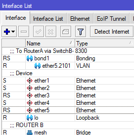
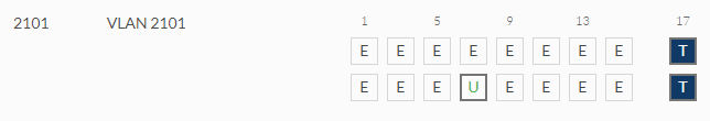
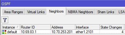
Juniper Point-to-Point Guide
Note: This guide is even further in-depth than the Point-to-Point configuration guide. This is only intended for a technical audience who is looking to create an NYCMesh P2P, when one or both sides of the link is routed by a Juniper router.
Overview
To create a mesh-specific OSPF P2P link on the Juniper, there are 4 configuration changes you will need to make
- Create an irb interface - creating an irb interface is the Juniper equivalent of creating a MikroTik VLAN interface, or a Brocade virtual interface (ve). It's an interface with an IP address, that is assigned to a certain VLAN. The only difference is that this VLAN is not limited to a port, and can be sent out any port. This is where you will assign your /30 P2P IP address.
- Create a VLAN - the VLAN and the irb interface are be linked together, and the VLAN is assigned to the switch port that the P2P traffic will come from. This will either be a switchport that the antenna is directly connected to, or a switchport that goes to another switch, which is connected to the antenna.
- Configure OSPF on the irb - this is where you configure the OSPF cost of your P2P.
- Add the VLAN to a switchport - this is where you assign the VLAN to the port where P2P traffic will be coming from on the Juniper
Prerequisites
- Subnet allocated using the IP Ranges spreadsheet
- P2P already configured on the MikroTik side of the link (follow this guide)
- Note that for the Mikrotik IP address, you need to set the IP address to
<IP_ADDRESS>/30, and the Network will automatically set itself to the correct /30 base address
- Note that for the Mikrotik IP address, you need to set the IP address to
- OSPF cost known
Choosing a VLAN ID
In order to create a P2P, we need to choose an unused VLAN on the Juniper.
- Log into the Juniper with
ssh root@ip_address - Enter
cliat the initial prompt to enter the switch configuration - Enter
show vlansand press enter. This will display a list of all the VLANs on the Juniper. Note down a tag that is unused (this can be anything between 1 and 4094, but you should keep it close to other existing VLANs)
Configuring the Juniper
- At the main Juniper CLI prompt (where you should be after entering
show vlansabove), enterconfigureto start configuring the router. - First, we'll create the irb. Enter the following commands, replacing
<P2P_NAME>with the name of your P2P link, and<IP_ADDRESS>with the IP address of the Juniper side of the link.set interfaces irb unit <VLAN_TAG> description <P2P NAME>set interfaces irb unit <VLAN_TAG> family inet address <IP_ADDRESS>/30
- Next, create a VLAN and link it to your irb interface, replacing variables as needed.
set vlans <P2P_NAME> vlan-id <VLAN_TAG>set vlans <P2P_NAME> l3-interface irb.<VLAN_TAG>
- Next, configure OSPF on the interface. Note the PTMP setting, meaning the OSPF configuration is Point to Multi Point and not Point to Point, NBMA (Non-Broadcast Multiple Access), or Broadcast (more info on the different types here)
set protocols ospf area 0.0.0.0 interface irb.<VLAN_TAG> interface-type p2mpset protocols ospf area 0.0.0.0 interface irb.<VLAN_TAG> metric <OSPF_COST>
- (Optional: if the MikroTik side of the link is using Bidirectional Forwarding Detection (aka BFD, a faster way of detecting when a link is down than the built-in OSPF method), configure that here. If you don't know, disregard these steps)
set protocols ospf area 0.0.0.0 interface irb.<VLAN_TAG> bfd-liveness-detection minimum-interval 200set protocols ospf area 0.0.0.0 interface irb.<VLAN_TAG> bfd-liveness-detection multiplier 5set protocols ospf area 0.0.0.0 interface irb.<VLAN_TAG> bfd-liveness-detection full-neighbors-only
- Now add the VLAN to the switchport where the P2P is coming from (usually a switch)
- To figure out what interface goes to which switch, enter the command
run show interfaces description. This will list all of the ports and their descriptions. Note the interface name (examplexe-0/0/4) that the switch or antenna is connected to. Note: if the switch is connected to a bond (known as ae interfaces in Juniper) be sure to add the vlan to that port. - Add the vlan with
set interfaces <INTERFACE> unit 0 family ethernet-switching vlan members <P2P_NAME>
- To figure out what interface goes to which switch, enter the command
- Type
committo save your configuration. Once the commit succeeds, typeexitto leave configuration mode. - If there are upstream switches that your P2P VLAN needs to be added to, add them normally according to the guide listed in prerequisites.
- To confirm OSPF comes up on the Juniper, enter
show ospf neighbor, and the router will give you a list of neighbors, and their connected interfaces.
10 Gigabit
This is adapted from the help page of a Bay Area ISP, Sonic.
Expected Speeds on Sonic 10 Gigabit Fiber
Sonic 10 Gigabit Fiber service is just like our 1 Gig service in terms of it's "All or nothing" bandwidth to your modem. The only limitation to this service is the equipment being used to provide the service to your end devices.
Even though 10G bandwidth is at the ONT (Fiber modem), getting that speed to your end devices depends on those devices and the Router you are using to get that speed to them. In some cases the "bottleneck" in speed is restricted due to common issues like using WiFi. WiFi typically "tops out" at around 500Mbps. Theoretically speeds of around 1,500Mbps could be possible, but only under the best conditions. These conditions being how much RF interference you have around your WiFi router. If you have more than 10+ WiFi connections around you when you look up your "available wireless networks", it will be harder for you to get the maximum possible speed due to all the interference from those neighboring signals. The more signals you have, the more overlap there is, resulting in slower than expected speeds. You'll also want to ensure your WiFi router is not near any other source of RF interference like within 3 ft of a speaker, sub-woofer, wireless telephone bases or microwave oven etc.
If you have your equipment placed in clean areas more than 3 feet from sources of RF interference, or you don't have a lot of neighboring WiFi signals to interfere with your WiFi signal yet you are still seeing slower than expected speeds, the issue may be with the external wire getting to your ONT. If you suspect this is the case with your service please reach out to Sonic Support for assistance.
Few customers today are able to utilize the full 10 Gigabit of bandwidth delivered to their ONT. You must have a device connected via Ethernet that is configured for and capable of 10 Gigabit speeds. As technology advances, Devices and routers capable achieving 10G speeds will become more readily available and it will be much easier to use the FULL bandwidth of 10G at that time. Detailed below are some real world examples of hardware and software configurations and the expected speeds for those configurations.
Connected via Ethernet
Ethernet is the recommended method of connecting your device to your Sonic Gigabit Fiber service to achieve maximum speed. If you are getting 100Mb/s on your 10 Gigabit Fiber connection your device may be configured for Fast Ethernet as opposed to Gigabit.
| Method of Connection | Age of Device | Expected Speeds |
|---|---|---|
| Ethernet Connector | 2010 or newer | 2Gb/s - 10Gb/s |
| Ethernet Connector | Older than 2010 | 100Mb/s |
| USB2 to Ethernet Adapter* | 2010 or newer | Up to 7Gb/s |
| USB3 to Ethernet Adapter* | 2014 or newer | Up to 10Gb/s |
Connected via WiFi
WiFi connectivity is ubiquitous and convenient, however the technology is not yet able to achieve true Gigabit speeds. Other factors that can affect WiFi speeds include the age of your device, the wireless protocol your device is utilizing, wireless interference, the distance your device is from the router, and whether you have a gigabit wireless adapter. Wireless connectivity is susceptible to a variety of external influences that may negatively impact speeds but you can mitigate many of them by troubleshooting. To troubleshoot WiFi consult our wireless troubleshooting guide.
| Wireless Protocol | Device Type | Expected WiFi Speeds |
|---|---|---|
| 802.11ac | High end computer | Up to 500Mb/s |
| 802.11ac | High end phone or tablet / computer | 100Mb/s - 500Mb/s |
| 802.11n | Phone or tablet / budget computer | Up to 300Mb/s |
| 802.11a/b/g | Devices manufactured before 2007 | Up to 100Mb/s |
WiFi 6 is here! What does this mean?
Wi-Fi 6, or 802.11ax is the newest version of the 802.11 standard for wireless network transmissions that people commonly call Wi-Fi. It's a backward-compatible upgrade over the previous version of the Wi-Fi standard, which is called 802.11ac. Wi-Fi 6 isn't a new means of connecting to the internet, it's an upgraded standard that compatible devices, particularly routers, can take advantage of to transmit Wi-Fi signals more efficiently.
Wi-Fi 6 is exciting because it solves one of the most significant current problems with Wi-Fi, how it can struggle to support multiple devices connecting to the same signal. This problem has become more notable in recent years as smartphones and smart devices have become more popular and the number of devices connecting to the same router or hotspot has multiplied.
WiFi 6 is capable of transmitting more speed over Radio waves which translates to a faster, more reliable connection when using WiFi. There are of course external factors that can impact the speed you can achieve such as the once we mentioned above. WiFi 6 capable routers can provide on average 1,320 Mbps. That's about 40% faster than the fastest Wi-Fi 5 speed we've ever measured, which is 938 Mbps!
Gigabit-plus speeds like this are a lot more than you're likely to ever need from a single device. In environments with a lot of devices that need to connect, Wi-Fi 6 will make a huge difference. In small homes with only a few devices on the network, the difference might be harder to notice. With more and more businesses now restricting their content to the cloud, Faster access speeds will become the mainstay in the future.
Connected via WiFi 6
WiFi connectivity is ubiquitous and convenient, however the technology is not yet able to achieve true Gigabit speeds. Other factors that can affect WiFi speeds include the age of your device, the wireless protocol your device is utilizing, wireless interference, the distance your device is from the router, and whether you have a gigabit wireless adapter. Wireless connectivity is susceptible to a variety of external influences that may negatively impact speeds but you can mitigate many of them by troubleshooting. To troubleshoot WiFi consult our wireless troubleshooting guide.
| Wireless Protocol | Device Type | Expected WiFi Speeds |
|---|---|---|
| 802.11ax | High end computer | 500Mb/s up to 1,500Mb/s |
| 802.11ax | High end phone or tablet / computer | 300Mb/s - 1,500Mb/s+ |
| 802.11n | Phone or tablet / budget computer | Up to 300Mb/s |
| 802.11a/b/g | Devices manufactured before 2007 | Up to 100Mb/s |
Brocade Router CLI Notes
Overview
This ICX6610 network switch may be capable of acting as a core router for a large site in the Mesh. However, it does not support Point to Multi Point (P2MP/PTMP) OSPF which is necessary to talk to the rest of the Mesh network
It provides 802.3at PoE+ power to all of its 48 ports (or 24 ports on the ICX6610-24P), has 10 SFP+ 10G ports on the front, 2 QSFP+ 40G ports on the back, and then 2 QSFP+ ports that can only operate as 4x10G SFP+ breakout cables.
The 40G ports can be used to connect a hub to dark fiber running to a data center, which is how the Juniper QFX5100-48S at Grand St is set up. The QSFP+ to 4x 10G SFP+ ports can be used with Direct Attach Cables (DACs) to connect to other rackmount gear, such as a Ubiquiti PON OLT for in-building fiber to the apartment. The SFP+ ports on the front can be used in a similar way to the Mikrotik CCR2004, connecting fiber runs to a roof rack, Mikrotik netPower 16P, Ubiquiti Wave APs, Siklu EtherHaul 8010FX, etc. The PoE ports can be used to power any device compatible with 802.3af/at active PoE, such as "rabbit ear" Ubiquiti AC Mesh Access Points (APs), IP cameras, IP phones, and even Ubiquiti PoE converters to provide passive 24V PoE.
The switch also has advanced L3 functionality and can also perform routing duties. It supports OSPF, DHCP Server, VLANs, and more.
It is configured either with a DB9/RS232/Serial Console Cable (a Cisco cable works), or via SSH. There is also a Web UI with limited functionality.
The switch has an 800MHz PowerPC processor, 512MB RAM, and runs FastIron OS, which is very similar to Cisco's IOS. The latest software update for the ICX6610 as of 2024Q1 was 2020-04-29 with release 08.0.30u. A used ICX6610-48P was purchased off Ebay for $150 in 2024Q1 for Olmsted NN584, its stock serial number is BXK2526J0YG and its stock software was 08.0.30t (from 2019-02-18) with boot monitor 10.1.00T7f5
Initial Setup - Firmware and License
- The original instructions can be found here and here with a Youtube version here
- This initial setup requires a TFTP server to be running, serving the files needed for these steps. Assume for this example that the TFTP server's IP is 10.97.227.164
- Connect the Management RJ45 port in the back of the switch to the network the TFTP server is connected to. Also connect the Console cable and get the
screenorminicomconsole session going, ready to receive printout from the switch while it boots - Connect power while hitting
Bon the console keyboard to interrupt the boot process and enter the Boot Monitor prompt. If the line is filled withbbb, press Enter to clear to get to a new line
ICX Boot Code Version 10.1.00 (grz10100)
Enter 'a' to stop at memory test
Enter 'b' to stop at boot monitor
***** Interrupted by entering 'b' *****
.BOOT INFO: load monitor from boot flash, cksum = 71f1
BOOT INFO: verify flash files.......
Monitor>bbb
Not found in command table, 'bbb'
Monitor>
- Give the switch a static IP on the same network as the TFTP server. In this example, the switch is 10.97.227.165 so it can connect to the TFTP server 10.97.227.164
Monitor>ip address 10.97.227.165
IP address = 10.97.227.165
IP subnet mask = 255.255.255.0
Monitor>
- Update the Boot Monitor and the main software using TFTP, first with
copy tftp flash 10.97.227.164 ICX6610-FCX/grz10100.bin bootand then withcopy tftp flash 10.97.227.164 ICX6610-FCX/FCXR08030u.bin primary
Monitor>copy tftp flash 10.97.227.164 ICX6610-FCX/grz10100.bin boot
Loading image from Tftp
............................................Done
Programming boot flash, please wait..
Erasing....
Writing
Done
Monitor>copy tftp flash 10.97.227.164 ICX6610-FCX/FCXR08030u.bin primary
.......................................Done
.Monitor>
- Erase the config (reset to factory defaults) with
factory set-defaultand theny
Monitor>factory set-default
This command will remove configuration and keys detail.
Do you want to continue? (Y/N) y
Done.
Monitor>
- Finally, reboot the switch to apply the fresh software and settings with
reset. This will take a couple minutes.
Monitor>reset
$
ICX Boot Code Version 10.1.00 (grz10100)
Enter 'a' to stop at memory test
Enter 'b' to stop at boot monitor
.BOOT INFO: load monitor from boot flash, cksum = 71f1
BOOT INFO: verify flash files......
BOOT INFO: load image from primary copy...
- After a couple minutes, the console may be printing repeated
TFTP session timed outlines. PressENTERto get past the messages and to a prompt.
PoE Info: PoE module 1 of Unit 1 initialization is done.
TFTP session timed out
TFTP session timed out
TFTP session timed out
ICX6610-48P Router>
- Enter the configuration mode with
enableand thenconfigure terminal. Then disable the DHCP client withip dhcp-client disable
ICX6610-48P Router>
ICX6610-48P Router>enable
No password has been assigned yet...
ICX6610-48P Router#configure terminal
ICX6610-48P Router(config)#TFTP session timed out
ICX6610-48P Router(config)#ip dhcp-client disable
ICX6610-48P Router(config)#
- Now give the switch a static IP address. All ports are VLAN1 by default. Give VLAN1 its own virtual interface, and then assign that virtual interface an IP address (the same as before). Then write the memory to save these settings as permanent
ICX6610-48P Router(config)#vlan 1
ICX6610-48P Router(config-vlan-1)#router-interface ve 1
ICX6610-48P Router(config-vlan-1)#exit
ICX6610-48P Router(config)#interface ve 1
ICX6610-48P Router(config-vif-1)#ip address 10.97.227.165/24
ICX6610-48P Router(config-vif-1)#exit
ICX6610-48P Router(config)#write memory
Write startup-config done.
ICX6610-48P Router(config)#exit
ICX6610-48P Router#
- Disconnect the Ethernet cable from the management port and move it to any of the ports on the front of the switch. Otherwise, the TFTP connection won't work in the next steps
- Now update the PoE module firmware (one per switch, this is not related to the power supplies), again using the TFTP server, with
inline power install-firmware stack-unit 1 tftp 10.97.227.164 ICX6610-FCX/fcx_poeplus_02.1.0.b004.fw
ICX6610-48P Router#inline power install-firmware stack-unit 1 tftp 10.97.227.164 ICX6610-FCX/fcx_poeplus_02.1.0.b004.fw
ICX6610-48P Router#Flash Memory Write (8192 bytes per dot) ...........
tftp download successful file name = poe-fw
Sending PoE Firmware to Unit 1.
ICX6610-48P Router#
- Use
show logto monitor the update process, which may take 10 minutes.
ICX6610-48P Router#show log
Syslog logging: enabled ( 0 messages dropped, 0 flushes, 0 overruns)
Buffer logging: level ACDMEINW, 14 messages logged
level code: A=alert C=critical D=debugging M=emergency E=error
I=informational N=notification W=warning
Static Log Buffer:
00 days 00h02m39s:I:System: Stack unit 1 POE Power supply 1 with 748000 mwatts capacity is up
00 days 00h02m39s:I:System: Stack unit 1 POE Power supply 2 with 748000 mwatts capacity is up
Dynamic Log Buffer (50 lines):
00 days 00h06m00s:I:System: U1-MSG: PoE Info: Firmware Download on slot 1.....40 percent completed.
00 days 00h05m25s:I:System: U1-MSG: PoE Info: Firmware Download on slot 1.....30 percent completed.
- Reboot using
reloadonce the firmware is updated. The switch won't let the reboot occur until the update is complete
ICX6610-48P Router#reload
Are you sure? (enter 'y' or 'n'): Rebooting(0)...
y
ICX6610-48P Router#*
$
ICX Boot Code Version 10.1.00 (grz10100)
Enter 'a' to stop at memory test
Enter 'b' to stop at boot monitor
- Now get into privileged mode with
enable, then update the serial number in the software to match the license that will be applied next, and reboot
ICX6610-48P Router>enable
No password has been assigned yet...
ICX6610-48P Router#hw pid-prom serial 2ax5o2jk68e
ICX6610-48P Router#hw pid-prom clear-sw-lid
ICX6610-48P Router#reload
Are you sure? (enter 'y' or 'n'): Rebooting(0)...
y
ICX6610-48P Router#*
$
ICX Boot Code Version 10.1.00 (grz10100)
- Now re-enter the privileged mode and use TFTP to copy over the license files
ICX6610-48P Router>enable
No password has been assigned yet...
ICX6610-48P Router#copy tftp license 10.97.227.164 ICX6610-FCX/1-6610-ports.xml unit 1
ICX6610-48P Router#Flash Memory Write (8192 bytes per dot) .
Copy Software License from TFTP to Flash Done.
ICX6610-48P Router#copy tftp license 10.97.227.164 ICX6610-FCX/2-6610-adv.xml unit 1
ICX6610-48P Router#Flash Memory Write (8192 bytes per dot) .
Copy Software License from TFTP to Flash Done.
copy tftp license 10.97.227.164 ICX6610-FCX/3-6610-macsec.xml unit 1
ICX6610-48P Router#Flash Memory Write (8192 bytes per dot) .
Copy Software License from TFTP to Flash Done.
- Use
show licenseto confirm that the license has been applied and the 10G ports are usable
ICX6610-48P Router#show license
Index Lic Mode Lic Name Lid/Serial No Lic Type Status Lic Period Lic Capacity
Stack unit 1:
1 Node Lock ICX6610-10G-LIC-POD H4CKTH3PLN8 Normal Active Unlimited 8
2 Node Lock ICX6610-ADV-LIC-SW H4CKTH3PLN8 Normal Active Unlimited 1
3 Node Lock ICX-MACSEC-LIC H4CKTH3PLN8 Normal Active Unlimited 1
ICX6610-48P Router#
- Finally, run
write memoryto save all the settings so far as permanent
ICX6610-48P Router#write memory
ICX6610-48P Router#Flash Memory Write <8192 bytes per dot> .
Copy Done.
ICX6610-48P Router#
Initial Setup - System
- Enable SSH access to the management command line by first generating an RSA keypair. Then create a username and password. Then enable that username and password to allow logins via SSH and the Web UI. Also disable the Telnet server. Then save the settings
- Optionally,
enable aaa consolecan be added to force a password on the console. JohnB skipped this step since the passwords are all placeholders anyway
- Optionally,
ICX6610-48P Router>enable
ICX6610-48P Router#configure terminal
ICX6610-48P Router(config)#crypto key zeroize
RSA Key pair not found
ICX6610-48P Router(config)#crypto key generate rsa modulus 2048
ICX6610-48P Router(config)#
Creating RSA key pair, please wait...
RSA Key pair is successfully created
ICX6610-48P Router(config)#username root password <mesh password here>
ICX6610-48P Router(config)#aaa authentication login default local
ICX6610-48P Router(config)#aaa authentication web default local
ICX6610-48P Router(config)#no telnet server
ICX6610-48P Router(config)#write mem
- To actually connect via SSH, some special arguments need to be passed in to support the key exchange and host key algorithms supported by the switch
-
ssh -oKexAlgorithms=+diffie-hellman-group1-sha1 -oHostKeyAlgorithms=+ssh-rsa root@10.97.227.165 - https://unix.stackexchange.com/questions/402746/ssh-unable-to-negotiate-no-matching-key-exchange-method-found
- https://askubuntu.com/questions/836048/ssh-returns-no-matching-host-key-type-found-their-offer-ssh-dss
-
- The hostname is by default
ICX6610-48P Routeras seen in the first part of every command line. This can be changed withhostname <newname>. For Olmsted, this has been changed tohostname nycmesh-nn584-brocade-poe-switchor possiblyhostname nycmesh-nn584-brocade-core - To configure the switch's DNS server, https://wiki.mesh.nycmesh.net/link/92 shows that
10.10.10.10is the server of choice for the Mesh.
ICX6610-48P Router>enable
ICX6610-48P Router#configure terminal
ICX6610-48P Router(config)#ip dns server-address 10.10.10.10
- TODO: To configure the default route for the switch, the
ip routecommand can be run. But this may conflict with the OSPF routing table according to Olivier
ICX6610-48P Router>enable
ICX6610-48P Router#configure terminal
ICX6610-48P Router(config)#ip route 0.0.0.0/0 10.69.69.69
- To configure NTP, set Daylight Savings to be enabled, pick the time zone, enter the NTP configuration, disable serving NTP to clients, pick the IP addresses of the NTP servers to source from (maximum support for 8 IPs) and then exit and save
- NOTE that
no ntpwill reset the configuration - The IP for NTP is 10.10.10.123
- NOTE that
clock summer-time
clock timezone gmt GMT-05
ntp
disable serve
server 10.10.10.123
exit
- The NTP status can be checked with
show ntp associationsandshow ntp status - To enable SNMPv2 for statistics gathering, run
snmp-server community public ro - To enable optical module monitoring, run the
optical monitorcommand
ICX6610-48P Router>enable
ICX6610-48P Router#configure terminal
ICX6610-48P Router(config)#optical-monitor
Initial Setup - Ports
- To use the 40G ports on the back of the switch, they need to be removed from the switch stacking configuration
- With its factory settings
show runwill showstack-trunklines claiming usage of the 40G ports in module 2 (the last two lines)
stack unit 1
module 1 icx6610-48-port-management-module
module 2 icx6610-qsfp-10-port-160g-module
module 3 icx6610-8-port-10g-dual-mode-module
stack-trunk 1/2/1 to 1/2/2
stack-trunk 1/2/6 to 1/2/7
!
- Go into privileged and then configuration mode and remove the
stack-trunksettings, and disable the stack. Then save the settings withwrite mem
ICX6610-48P Router>enable
ICX6610-48P Router#configure terminal
ICX6610-48P Router(config)#stack unit 1
ICX6610-48P Router(config-unit-1)#no stack-trunk 1/2/1 to 1/2/2
ICX6610-48P Router(config-unit-1)#no stack-trunk 1/2/6 to 1/2/7
ICX6610-48P Router(config-unit-1)#stack disable
ICX6610-48P Router(config-unit-1)#exit
ICX6610-48P Router(config)#write mem
- Now use
show runagain to confirm the configuration has changed
ICX6610-48P Router(config)#show run
Current configuration:
!
ver 08.0.30uT7f3
!
stack unit 1st
module 1 icx6610-48p-poe-port-management-module
module 2 icx6610-qsfp-10-port-160g-module
module 3 icx6610-8-port-10g-dual-mode-module
stack disable
!
- Next, configure the 8 SFP+ ports to operate explicitly at 10G speeds with
speed-duplexcommands. The interfaces can all be configured at the same time. Note that if a module is installed that is 1G and not 10G, an error will be shown.- TODO: Unclear if setting
speed-duplex autoinstead ofspeed-duplex 10g-fullwould also work fine. If not, setting the 1G interfaces tospeed-duplex 1000-fullshould work, as per the command reference PDF. Alternatively, theno speed-duplexwill reset the interface to its default settings
- TODO: Unclear if setting
ICX6610-48P Router>enable
ICX6610-48P Router#configure terminal
ICX6610-48P Router(config)#interface ethernet 1/3/1 to 1/3/8
ICX6610-48P Router(config-mif-1/3/1-1/3/8)#speed-duplex 10g-full
INFO: 1/3/3: optics <-> speed mismatch. Replace with SFP+ to enable link.
ICX6610-48P Router(config-mif-1/3/1-1/3/8)#write mem
Write startup-config done.
- Next, configure all 48 RJ45 ports on the switch to have Active 802.3af/at PoE enabled. Otherwise, they will just act as unpowered ports.
ICX6610-48P Router>enable
ICX6610-48P Router#configure terminal
ICX6610-48P Router(config)#interface ethernet 1/1/1 to 1/1/48
ICX6610-48P Router(config-mif-1/1/1-1/1/48)#inline power
ICX6610-48P Router(config-mif-1/1/1-1/1/48)#write mem
- Also, disable legacy PoE as it can accidentally enable and fry devices sometimes, since it's based on resistance over pairs of wires
ICX6610-48P Router>enable
ICX6610-48P Router#configure terminal
ICX6610-48P Router(config)#stack unit 1
ICX6610-48P Router(config-unit-1)#no legacy-inline-power
ICX6610-48P Router(config-unit-1)#write mem
- PoE power status can be seen with
show inline powerorshow inline power detailorshow inline power detail 1/1/5for a specific device
TODO add printouts
Networking Setup
- TODO
- Tagged/trunk port
- Untagged port VLAN assignment
- 802.3ad LACP link aggregation https://fohdeesha.com/docs/icx6xxx-adv.html
- Link Aggregation
- Create a LAG with
lag <lagname> dynamicand that will enter into the configuration for the new LAG. Name itnetpowerfor the two 10G links to the Netpower on the roof of Olmsted - Add ports to the LAG, in this case the two 10G SFP+ ports
ports ethernet 1/3/1 ethernet 1/3/2 - Specify the primary port with
primary-port 1/3/1. NOTE that all future configurations applied to 1/3/1 will auto-apply to the other members in the LAG, such as tagging it with a VLANtag interface ethernet 1/3/1 - Deploy the LAG with
deploy - Check the status of the deployed LAG with
show lagand look for theOpeoutput column. If it shows asOpethat means it's operational, otherwise it might showErrorBlofor error/blocked
- Create a LAG with
Common Commands
- More commands can be found in the Ruckus FastIron Command Reference PDF, a 1300-page monster. A free Ruckus account is needed to download (or ask JohnB)
-
?at any point will list the commands available - The Tab key can auto-complete commands
device(config)#show li
license Show software license information
link-error-disable Link Debouncing Control
link-keepalive Link Layer Keepalive
- Immediately after logging in, the switch will be in User EXEC mode, which is read-only and has limited diagnostic commands available (ping, traceroute). To access more commands, enter into Privileged EXEC mode with
enable. The prompt will change from>to#to indicate this state change.
ICX6610-48P Router>enable
ICX6610-48P Router#
- Global Configuration Mode is needed to actually make changes to the switch's ports and overall system settings. This can be done after running
enableby following up withconfigure terminalor a shortened version,conf t. The prompt will change to include(config)to indicate the mode
ICX6610-48P Router>enable
ICX6610-48P Router#configure terminal
ICX6610-48P Router(config)#
-
write memoryor the shortenedwrite memis needed to save the settings applied as permanent. Otherwise, a reboot will wipe any modified settings. The command may or may not output a status line
ICX6610-48P Router(config)#write memory
ICX6610-48P Router(config)#Flash Memory Write <8192 bytes per dot> .
Copy Done.
ICX6610-48P Router(config)#
-
show runwill show all the current settings on the switch, similar to/exporton Mikrotik.
ICX6610-48P Router(config)#show run
Current configuration:
!
ver 08.0.30uT7f3
!
stack unit 1st
module 1 icx6610-48p-poe-port-management-module
module 2 icx6610-qsfp-10-port-160g-module
module 3 icx6610-8-port-10g-dual-mode-module
stack disable
!
!
!
!
vlan 1 name DEFAULT-VLAN by portv
router-interface ve 1
!
<continues>
- Configure a specific port with the
interface ethernet X/Y/Zcommand, or multiple ports with theinterface ethernet X/Y/Z to A/B/Ccommand
device(config)# interface ethernet 1/1/1
device(config-if-e1000-1/1/1)#
device(config)# interface ethernet 1/1/1 to 1/1/48
device(config-mif-1/1/1-1/1/48)#
- Adding
nobefore a command will remove all configuration related to it. For example, runningno interface ethernet 1/1/1will reset its configuration - To see fan and temperature status,
show chassiscan be used
The stack unit 1 chassis info:
Power supply 1 (AC - PoE) present, status ok
Model Number: 23-0000142-02
Serial Number: JJ4
Firmware Ver: A
Power supply 1 Fan Air Flow Direction: Front to Back
Power supply 2 (AC - PoE) present, status ok
Model Number: 23-0000142-02
Serial Number: P11
Firmware Ver: A
Power supply 2 Fan Air Flow Direction: Front to Back
Fan 1 ok, speed (auto): [[1]]<->2
Fan 2 ok, speed (auto): [[1]]<->2
Fan controlled temperature: 51.5 deg-C
Fan speed switching temperature thresholds:
Speed 1: NM<----->84 deg-C
Speed 2: 79<-----> 87 deg-C (shutdown)
Fan 1 Air Flow Direction: Front to Back
Fan 2 Air Flow Direction: Front to Back
MAC 1 Temperature Readings:
Current temperature : 36.5 deg-C
MAC 2 Temperature Readings:
Current temperature : 43.0 deg-C
CPU Temperature Readings:
Current temperature : 51.0 deg-C
sensor A Temperature Readings:
Current temperature : 41.5 deg-C
sensor B Temperature Readings:
Current temperature : 43.0 deg-C
sensor C Temperature Readings:
Current temperature : 31.0 deg-C
stacking card Temperature Readings:
Current temperature : 47.0 deg-C
Warning level.......: 77.0 deg-C
Shutdown level......: 87.0 deg-C
Boot Prom MAC : 748e.f8fe.b92a
Management MAC: 748e.f8fe.b92a
- To see port flapping or other events, the system log can be accessed with
show log
Apr 2 21:43:23:O:SYSTEM: Optic is not Brocade qualified (port 1/3/1).
Apr 2 21:41:01:O:SYSTEM: Optic is not Brocade qualified (port 1/3/3).
Apr 2 21:41:01:O:SYSTEM: Optic is not Brocade qualified (port 1/3/2).
Apr 2 21:40:53:I:System: Interface ethernet 1/3/2, state up
Apr 2 21:40:52:I:System: Interface ethernet 1/3/2, state down
Apr 2 21:40:52:I:System: Interface ethernet 1/3/2, state up
Apr 2 21:40:31:O:SYSTEM: Optic is not Brocade qualified (port 1/3/4).
Apr 2 21:40:21:O:SYSTEM: Optic is not Brocade qualified (port 1/3/1).
- To name a port to describe its use, first select it and then use
port-name <someName>
interface ethernet 1/3/1
port-name netpower-primary
write mem
- See a shortened version of all the interfaces with
show interface briefor specify a specific interface after to see just that one, sayshow interfaces brief ethernet 1/3/1
Port Link State Dupl Speed Trunk Tag Pvid Pri MAC Name
1/3/1 Up Forward Full 10G None Yes N/A 0 748e.f8fe.b92a ccr1009
- Enable dual-mode tagged and untagged VLAN port behavior with
dual-mode. Pass in a VLAN ID to automatically tag all untagged traffic as the VLAN ID (PVID).show interfaces briefwill show the PVID for the interfaces, as well as if it's tagged. The PVID will be removed if tagged traffic is added, by default- https://docs.ruckuswireless.com/fastiron/08.0.60/fastiron-08060-l2guide/GUID-9B341D5A-7576-41BA-AC85-F75F9340A0A7.html
- Show bandwidth information for a given port with
show statistics ethernet 1/3/2
Port Link State Dupl Speed Trunk Tag Pvid Pri MAC Name
1/3/2 Up Forward Full 1G None Yes N/A 0 748e.f8fe.b92a hexS
Port 1/3/2 Counters:
InOctets 125802 OutOctets 27074027
InPkts 433 OutPkts 310130
InBroadcastPkts 33 OutBroadcastPkts 302
InMulticastPkts 90 OutMulticastPkts 309492
InUnicastPkts 310 OutUnicastPkts 336
InBadPkts 0
InFragments 0
InDiscards 0 OutErrors 0
CRC 0 Collisions 0
InErrors 0 LateCollisions 0
InGiantPkts 0
InShortPkts 0
InJabber 0
InFlowCtrlPkts 0 OutFlowCtrlPkts 0
InBitsPerSec 2168 OutBitsPerSec 588056
InPktsPerSec 0 OutPktsPerSec 842
InUtilization 0.00% OutUtilization 0.06%
- Show information about an SFP optic with
show optic 1/3/1
- Show detailed PoE information with
show inline power detail
Power Supply Data On stack 1:
++++++++++++++++++
Power Supply Data:
++++++++++++++++++
Power Supply #1:
Max Curr: 13.6 Amps
Voltage: 55.0 Volts
Capacity: 748 Watts
Power Supply #2:
Max Curr: 13.6 Amps
Voltage: 55.0 Volts
Capacity: 748 Watts
POE Details Info. On Stack 1 :
General PoE Data:
+++++++++++++++++
Firmware
Version
----------------
02.1.0 Build 004
Cumulative Port State Data:
+++++++++++++++++++++++++++
#Ports #Ports #Ports #Ports #Ports #Ports #Ports
Admin-On Admin-Off Oper-On Oper-Off Off-Denied Off-No-PD Off-Fault
-------------------------------------------------------------------------
48 0 1 47 0 47 4
Cumulative Port Power Data:
+++++++++++++++++++++++++++
#Ports #Ports #Ports Power Power
Pri: 1 Pri: 2 Pri: 3 Consumption Allocation
-----------------------------------------------
0 0 48 2.400 W 30.0 W
- Alternatively, show power status for all ports with
show inline power
Power Capacity: Total is 1496000 mWatts. Current Free is 1466000 mWatts.
Power Allocations: Requests Honored 61 times
Port Admin Oper ---Power(mWatts)--- PD Type PD Class Pri Fault/
State State Consumed Allocated Error
--------------------------------------------------------------------------
1/1/1 On Off 0 0 n/a n/a 3 n/a
1/1/2 On On 2300 30000 802.3at Class 4 3 n/a
1/1/3 On Off 0 0 n/a n/a 3 n/a
1/1/4 On Off 0 0 n/a n/a 3 n/a
1/1/5 On Off 0 0 n/a n/a 3 n/a
1/1/6 On Off 0 0 n/a n/a 3 n/a
1/1/7 On Off 0 0 n/a n/a 3 non-standard PD
1/1/8 On Off 0 0 n/a n/a 3 n/a
1/1/9 On Off 0 0 n/a n/a 3 n/a
1/1/10 On Off 0 0 n/a n/a 3 n/a
1/1/11 On Off 0 0 n/a n/a 3 n/a
1/1/12 On Off 0 0 n/a n/a 3 n/a
1/1/13 On Off 0 0 n/a n/a 3 n/a
1/1/14 On Off 0 0 n/a n/a 3 n/a
1/1/15 On Off 0 0 n/a n/a 3 n/a
1/1/16 On Off 0 0 n/a n/a 3 n/a
1/1/17 On Off 0 0 n/a n/a 3 n/a
1/1/18 On Off 0 0 n/a n/a 3 n/a
1/1/19 On Off 0 0 n/a n/a 3 n/a
1/1/20 On Off 0 0 n/a n/a 3 n/a
1/1/21 On Off 0 0 n/a n/a 3 n/a
1/1/22 On Off 0 0 n/a n/a 3 n/a
1/1/23 On Off 0 0 n/a n/a 3 n/a
1/1/24 On Off 0 0 n/a n/a 3 n/a
1/1/25 On Off 0 0 n/a n/a 3 n/a
1/1/26 On Off 0 0 n/a n/a 3 n/a
1/1/27 On Off 0 0 n/a n/a 3 n/a
1/1/28 On Off 0 0 n/a n/a 3 n/a
1/1/29 On Off 0 0 n/a n/a 3 n/a
1/1/30 On Off 0 0 n/a n/a 3 n/a
1/1/31 On Off 0 0 n/a n/a 3 n/a
1/1/32 On Off 0 0 n/a n/a 3 n/a
1/1/33 On Off 0 0 n/a n/a 3 n/a
1/1/34 On Off 0 0 n/a n/a 3 n/a
1/1/35 On Off 0 0 n/a n/a 3 n/a
1/1/36 On Off 0 0 n/a n/a 3 n/a
1/1/37 On Off 0 0 n/a n/a 3 n/a
1/1/38 On Off 0 0 n/a n/a 3 non-standard PD
1/1/39 On Off 0 0 n/a n/a 3 n/a
1/1/40 On Off 0 0 n/a n/a 3 n/a
1/1/41 On Off 0 0 n/a n/a 3 n/a
1/1/42 On Off 0 0 n/a n/a 3 n/a
1/1/43 On Off 0 0 n/a n/a 3 n/a
1/1/44 On Off 0 0 n/a n/a 3 n/a
1/1/45 On Off 0 0 n/a n/a 3 n/a
1/1/46 On Off 0 0 n/a n/a 3 non-standard PD
1/1/47 On Off 0 0 n/a n/a 3 n/a
1/1/48 On Off 0 0 n/a n/a 3 non-standard PD
--------------------------------------------------------------------------
Total 2300 30000
Web UI
- TODO
Port & Interface IDs
Brocade, Cisco, Juniper, and others use the X/Y/Z format to identify the different interfaces in a switch.
- X identifies the stack unit, which would only be something other than 1 when there are multiple switches combined in a switch stack. This setup is not used in the Mesh.
- Y is used to identify the slot or module within a given switch. If a switch has modular ports, say an optional 10G module, the slot number would be different. The base ports are typically 1, and then the other modules are 2, 3, etc.
- Z is used to identify the specific port in a given module. In a 24 port switch, this would go up to 24
For the ICX6610, the IDs are as follows
- The RJ45 ports on the front are numbered 1 thru 48. They exist in module 1. Their IDs are thus 1/1/1 through 1/1/48.
- The 10G ports on the left front of the switch are numbered 1 thru 8. They exist in module 3. Their IDs are thus 1/3/1 through 1/3/8
- The 40G ports on the back of the switch are numbered 1 thru 8. They exist in module 2. The 40G-only ports are 1/2/1 and 1/2/6 and are closest to the console port. NOTE that the 40G-only ports will not operate in breakout mode, nor will they operate at 10G. The breakout-only ports are 1/2/2 thru 1/2/5 for the top port, and 1/2/7 thru 1/2/10 for the bottom port. These breakout ports are closest to the fan. NOTE that the breakout ports will not operate at 40G, and will only work as four 10G links
Console Cable
This was JohnB's first time needing to use a console cable to set up a device, so this section serves to familiarize a newcomer with the process.
Many IT devices such as APC UPS battery backups, Cisco switches, and Ubiquiti gear have an RJ45 port labeled "Console" that can be used to configure or talk to the device. In some cases, configuration must occur with this method before more convenient configuration methods such as SSH or a Web UI are available. These RJ45 ports can have different wiring methods, so an APC RJ45 to DB9 cable is electrically different from a Cisco RJ45 to DB9 cable.
A normal serial adapter (say a Raspberry Pi or an ESP8266 or Arduino or ESP32) will only work with 3.3V or 5V logic, and will be incompatible with the 12V signals needed to talk to the networking devices. A specific adapter cable is needed. Because the RJ45 wiring can be different depending on the manufacturer, it's better to get a USB to DB9 cable than a USB to RJ45 cable. The Eaton/Tripp Lite Keyspan adapter is the OG, but cheaper options with the Prolific PL2303 chip work fine as well (USB-A option or the USB-C option JohnB got).
Once the cable is plugged into a computer, it should show up in USB Devices or Device Manager, but it may not be immediately ready to use. JohnB got hung up on a Macbook Pro M1 running macOS 14.3 where the device showed up in System Report but was not showing up as a serial connection. As per the instructions, ls -ltr /dev/*usb* was supposed to show the device, but there were no matches. There might have been an issue with kext Kernel Extensions and the installer provided on the websites (Prolific driver, Cable Matters driver(SKU 201060), they're the same). What ended up working was to install the driver via the App Store. After that, the device showed up as /dev/tty.PL2303G-USBtoUART110 and /dev/cu.PL2303G-USBtoUART110. What's the difference? TTY devices are for calling into UNIX systems, whereas CU (Call-Up) devices are for calling out from them (eg, modems), so /dev/cu.* is the correct device to use
Now the connection can be made. Connect the RJ45 to DB9 cable of choice (the blue Cisco cable works fine for the Brocade switch) and plug it in to the console port on the switch. Plug in the USB end. The screen Terminal command works and is installed by default, and the console session can be started with screen /dev/cu.PL2303G-USBtoUART110 9600 where 9600 is the baud rate in bits per second (9600 is pretty universal). Power cycle the switch and it should immediately start outputting content. For example:
ICX Boot Code Version 10.1.00 (grz10100)
Enter 'a' to stop at memory test
Enter 'b' to stop at boot monitor
BOOT INFO: load monitor from boot flash, cksum = 71f1
BOOT INFO: verify flash files.........
BOOT INFO: load image from primary copy...
platform type = 12
PCIE-1 LTSSM status: 22
PCIE Switch status: 0
..............................
Firmware integrity checksum passed
JohnB found that backspace did not work, and a mis-type would require pushing ENTER to finish the command or CTRL + C to clear the line.
An alternative to screen is minicom which is recommended by some people. Minicom can be installed on macOS with Homebrew, for example brew install minicom. JohnB has yet to set up minicom so a TODO is to finish this section with usage details on Minicom. Thishas some good information
TFTP Setup
To update the software of the Brocade switch, a TFTP server needs to be running on the same network as the switch. This ServeTheHome user set up a websitewith detailed instructions.
JohnB's abbreviated TFTP setup notes are:
- Install Linux Mint (Ubuntu base)
-
Download the firmware files and extract them in the home directory. In this case, the files are in
/home/test/brocade-12-19-2023/ - Modify the permissions download directory with
chmod --recursive 777 /home/test/brocade-12-19-2023/, otherwise Permission Denied errors might show up - Install TFTP server with
sudo apt install tftpd-hpa - Modify TFTP server settings with
nano /etc/default/tftpd-hpato match the following lines. This will remove the username, set the root directory to serve as the TFTP-Content directory from the earlier extract, serve TFTP on port 69, and print extra information in the logs
TFTP_USERNAME="nobody"
TFTP_DIRECTORY="/home/test/brocade-12-19-2023/TFTP-Content"
TFTP_ADDRESS="0.0.0.0:69"
TFTP_OPTIONS="--secure -vvvv"
- Restart the service with
systemctl restart tftpd-hpato apply the settings - (Optional) Monitor the TFTP server's activity with
tail -F /var/log/syslog. This will show connection attempts, errors, transferred files, and more - (Optional) Test the TFTP server functionality with another computer. Assuming the TFTP server's IP is 10.1.1.2, use another computer and follow these instructions
- Connect to the TFTP server with
tftp 10.1.1.2and it should connect, dropping into atftp >prompt - Try to get a file with
get ICX6610-FCX/grz10100.binand it should copy it to the current working directory - Exit the TFTP prompt with
quit
- Connect to the TFTP server with
Resources
-
ServeTheHome forum thread where johnb found out about these https://forums.servethehome.com/index.php?threads/brocade-icx-series-cheap-powerful-10gbe-40gbe-switching.21107/
-
Useful info on Console/Serial cables, Screen, Minicom https://pbxbook.com/other/mac-tty.html
-
USB-C to Serial/DB9/Console cable with Prolific PL2303 chip https://www.amazon.com/Cable-Matters-Serial-Adapter-USB-C/dp/B075GV6VL1 (SKU 201060). macOS App Store driver https://apps.apple.com/us/app/pl2303-serial/id1624835354?mt=12
-
Fohdeesha TFTP and Brocade firmware setup https://fohdeesha.com/docs/brocade-overview.html
-
Fohdeesha ICX6610 firmware updating and initial configuration https://fohdeesha.com/docs/fcx.html
-
Fohdeesha ICX6610 SSH setup, DNS, NTP, PoE, etc https://fohdeesha.com/docs/icx6xxx-adv.html
-
Fohdeesha ICX6610 10G license unlocking https://fohdeesha.com/docs/6610.html
-
Youtube version of the setup process https://www.youtube.com/watch?v=yutgXiGZ4Y8
-
Mesh IP Network Number allocation (strategy 3, split the network number into two parts so NN584 becomes 10.69.5.84) https://wiki.mesh.nycmesh.net/link/94
-
Mesh Omni config generator, which gives some information on CIDR, IP, etc https://configgen.nycmesh.net/?version=v4.9&device=Omnitik5AC&template=omni-poe-ether5.rsc.tmpl
-
Mesh Juniper vs Mikrotik configuration detail https://wiki.mesh.nycmesh.net/link/127
2024/03/12 Notes
-
show ip interfaceto get output about the virtual interfaces attached to VLANs
SSH@nycmesh-nn584-brocade-poe-switch#show ip interface
Interface IP-Address OK? Method Status Protocol VRF
Ve 1 10.69.5.84 YES manual up up default-vrf
10.97.227.165
Ve 10 10.10.10.10 YES manual up up default-vrf
- once entered into a VLAN, say with
vlan 11then runningno untagged ethernet 1/2/6would remove the interface from that VLAN. Theshow interfaces briefshould show the PVID to have changed to the VLAN ID if the ports were set to untagged - Then create a virtual interface to go with that VLAN, say
interface ve 11and then add an IP/network to it withip address 10.70.196.1/23 - Create a DHCP pool with
ip dhcp-server pool meshbridgewhich does not yet have an address space or network associated with it. Set the network withnetwork 10.96.146.0/26and then set the first section of the range as excluded withexcluded-address 10.96.146.1 10.96.146.10. Thenshow runshould show the configured DHCP server info:
ip dhcp-server pool meshbridge
excluded-address 10.96.146.1 10.96.146.10
lease 1 0 0
network 10.96.146.0 255.255.255.192
!
- https://www.reddit.com/r/networking/comments/5ivjji/i_dont_understand_brocade_ves/ had some good descriptions of virtual interfaces (VEs)
vlan 100 name Example_VLAN
untag ethernet 1 to 10
router-interface ve100
interface ve 100
ip address 192.168.100.1/24
You build the VLAN, associate it with some interfaces, then associate a VE with the VLAN. That creates the map between the VLAN, interfaces, and VE. Then you configure the VE. It's a virtual interface. Traditionally, you would have a router connected to a switch. The switch would connect hosts, then pass a single network segment (aka VLAN 1 in today's terms) or multiple VLANs to a stand-alone router, which would have the IP address configured on a physical interface. These virtual Ethernet (VE) or switch virtual interfaces (SVIs) are the logical equivalent of a physical router port. Think of it is as a virtual router inside the switch. VEs/SVIs will allow you more flexibility in terms of having multiple networks be trunked over a single interface. The biggest caveat is that the VE will not come up until the vlan is assigned to the interface. So if you create VLAN 10, and then assign VE 10 to that. Until you assign an interface to Vlan10, you will not be able to access the VE
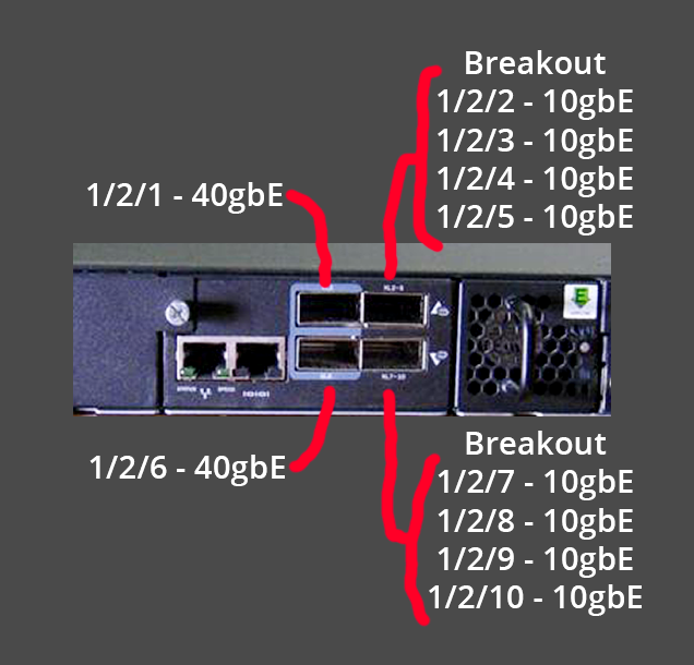
- For tagging Bonds/LACP/LAGs made up of multiple interfaces, one resource https://community.ruckuswireless.com/t5/ICX-Switches/tagging-a-VLAN-on-lag-port/m-p/29492/highlight/true noted that the lag can be added to a VLAN directly using its ID. For example:
config t
vlan 3000
tag lag 1
write mem
-
Someone else notes though that if the ports were in a vlan prior to the creation of the lag, those vlan tags should already be present (ports converted to lag syntax)
-
The brocade documentation notes
device(config)# vlan 2 name IP-Subnet_10.1.2.0/24
device(config-vlan-2)# untag ethernet 1 to 4
device(config-vlan-2)# tag ethernet 5 to 8
device(config-vlan-2)# router-interface ve 1
device(config-vlan-2)# interface ve 8
device(config-vif-8)# ip address 10.1.2.1/24
The first three commands in this example create a Layer 3 protocol-based VLAN name "IP-Subnet_10.1.2.0/24" and add a range of untagged and tagged ports to the VLAN. The last two commands move the configuration to the interface configuration mode for the virtual interface and assign an IP address to the interface. The router-interface command creates virtual interface 8 as the routing interface for the VLAN.
- Quincy looked up the IP ranges and started calculating ranges on the fly for Olmsted, NN584. First is the mesh bridge IP built from the node number, which in this case was 10.69.5.84/16 (not sure why the /16 was chosen).
- Then comes the second IP on the mesh bridge VLAN, this one being 10.96.146.1/26 which is the 64 address DHCP range allocated for this node number. Quincy got this from picking the 584th /26 after 10.69.5.84
- Then we need a DHCP range to address all the 400+ ONUs in the apartments. This selection is done manually. A /23 is chosen for its 512 addresses because a /24 would only be 256 addresses. Quincy picked 10.70.196.0/23 for this range
- Then we need a DHCP range for management devices (out-of-band or OOB) such as APs, battery backups, switches, and other devices. A /26 (64 addresses) would do but can be more annoying to keep track of, so a /24 (256 addresses) can be used. Quincy picked the network range of 10.70.198.0/24 with the VLAN virtual interface address being 10.70.198.1
- Finally, a network range is needed for the transit to the data center. Quincy picked a /30 which has two usable addresses (outside broadcast and the base network address) so 10.70.251.72/30 was chosen, meaning 10.70.251.73 and 10.70.251.74 are the usable addresses.
vlan 1 name DEFAULT-VLAN by port
router-interface ve 1
!
vlan 10 name meshbridge by port
tagged ethe 1/3/1 to 1/3/2
untagged ethe 1/1/47 to 1/1/48 ethe 1/3/3
router-interface ve 10
!
vlan 11 name OLTs by port
untagged ethe 1/2/2 to 1/2/5
router-interface ve 11
!
vlan 12 name OOB by port
tagged ethe 1/3/1 to 1/3/2
untagged ethe 1/1/40
router-interface ve 12
!
vlan 20 name Transit by port
untagged ethe 1/2/1
router-interface ve 20
interface ve 1
ip address 10.97.227.165 255.255.255.0
!
interface ve 10
ip address 10.69.5.84 255.255.0.0
ip address 10.96.146.1 255.255.255.192
!
interface ve 11
ip address 10.70.196.1 255.255.254.0
!
interface ve 12
ip address 10.70.198.1 255.255.255.0
!
interface ve 20
ip address 10.70.251.73 255.255.255.252
-
show ip intcan show all the active IP addresses running on the switch
SSH@nycmesh-nn584-brocade-poe-switch#show ip interface
Interface IP-Address OK? Method Status Protocol VRF
Ve 1 10.69.5.84 YES manual up up default-vrf
10.97.227.165
Ve 10 10.10.10.10 YES manual up up default-vrf
-
show lagcan show the current status of a deployed LAG/LACP/802.3ad/bond. The setup is also included
lag roof dynamic
ports ethernet 1/3/1 ethernet 1/3/2
primary-port ethernet 1/3/1
deploy
show lag
Total number of LAGs: 1
Total number of deployed LAGs: 1
Total number of trunks created:1 (119 available)
LACP System Priority / ID: 1 / 748e.f8fe.b92a
LACP Long timeout: 120, default: 120
LACP Short timeout: 3, default: 3
=== LAG "roof" ID 1 (dynamic Deployed) ===
LAG Configuration:
Ports: e 1/3/1 to 1/3/2
Port Count: 2
Primary Port: 1/3/1
Trunk Type: hash-based
LACP Key: 20001
Deployment: HW Trunk ID 1
Port Link State Dupl Speed Trunk Tag Pvid Pri MAC Name
1/3/1 Up Forward Full 10G 1 No 1 0 748e.f8fe.b92a
1/3/2 Up Forward Full 10G 1 No 1 0 748e.f8fe.b92a
Port [Sys P] [Port P] [ Key ] [Act][Tio][Agg][Syn][Col][Dis][Def][Exp][Ope]
1/3/1 1 1 20001 Yes L Agg Syn Col Dis No No Ope
1/3/2 1 1 20001 Yes L Agg Syn Col Dis No No Ope
Partner Info and PDU Statistics
Port Partner Partner LACP LACP
System ID Key Rx Count Tx Count
1/3/1 65535-48a9.8ae8.3388 15 4 4
1/3/2 65535-48a9.8ae8.3388 15 4 4
- Name interfaces for easy reference to what's plugged in:
enable
configure terminal
SSH@nycmesh-nn584-brocade-poe-switch(config-if-e10000-1/3/1)#interface ethernet 1/3/3
SSH@nycmesh-nn584-brocade-poe-switch(config-if-e10000-1/3/3)#port-name roof_fiber_3_rack_hex
SSH@nycmesh-nn584-brocade-poe-switch(config-if-e10000-1/3/3)#interface ethernet 1/3/1
SSH@nycmesh-nn584-brocade-poe-switch(config-if-e10000-1/3/1)#port-name roof_fiber_1_outside_netpower
SSH@nycmesh-nn584-brocade-poe-switch(config-if-e10000-1/3/1)#interface ethernet 1/1/47
SSH@nycmesh-nn584-brocade-poe-switch(config-if-e1000-1/1/47)#port-name ubiquiti_olt_mgmt
SSH@nycmesh-nn584-brocade-poe-switch(config-if-e1000-1/1/47)#interface ethernet 1/1/48
SSH@nycmesh-nn584-brocade-poe-switch(config-if-e1000-1/1/48)#port-name apc_ups_nmc_mgmt
SSH@nycmesh-nn584-brocade-poe-switch(config-if-e1000-1/1/48)#write mem
Write startup-config done.
- Set up DHCP
ip dhcp-server pool meshbridge
dns-server 10.10.10.10
domain-name nycmesh.net
excluded-address 10.96.146.1 10.96.146.10
lease 1 0 0
network 10.96.146.0 255.255.255.192
!
!
ip dhcp-server pool olts
dns-server 10.10.10.10
domain-name nycmesh.net
excluded-address 10.70.196.1 10.70.196.10
lease 1 0 0
network 10.70.196.0 255.255.254.0
!
!
ip dhcp-server pool oob
excluded-address 10.70.198.1 10.70.198.10
lease 1 0 0
network 10.70.198.0 255.255.255.0
!
- Here are the addresses we ended up setting, and their subnets/network ranges
interface ve 1
ip address 10.97.227.165 255.255.255.0
!
interface ve 10
ip address 10.69.5.84 255.255.0.0
ip address 10.96.146.1 255.255.255.192
!
interface ve 11
ip address 10.70.196.1 255.255.254.0
!
interface ve 20
ip address 10.70.251.73 255.255.255.252
!
- Show information about the SFP modules:
optical-monitor (to enable optic monitoring)
show media (to list all the different things installed in the different ports, shows the SFP module info)
Port 1/3/1: Type : 10GE LR 10km (SFP +)
Port 1/3/2: Type : 10GE LR 10km (SFP +)
Port 1/3/3: Type : 1G M-GBXD(SFP)
Port 1/3/4: Type : EMPTY
show optic 1/3/3 (should show information but doesn't)
show media validation (to show the detail on the optics)
Port Supported Vendor Type
----------------------------------------------------------------------
1/3/1 Yes FS Type : 10GE LR 10km (SFP +)
1/3/2 Yes FS Type : 10GE LR 10km (SFP +)
1/3/3 Yes FS Type : 1G M-GBXD(SFP)
show media ethernet 1/3/3 (shows more detail about the optic)
Port 1/3/3: Type : 1G M-GBXD(SFP)
Vendor: FS Version:
Part# : SFP-GE-BX Serial#: G2330171249
2024/03/19 Final Config Notes
- Starting Point
vlan 10 name meshbridge by port
tagged ethe 1/1/48
untagged ethe 1/1/1 to 1/1/6
vlan 11 name OLTs by port
tagged ethe 1/1/48
untagged ethe 1/1/7 to 1/1/12
vlan 12 name OOB by port
untagged ethe 1/1/13 to 1/1/18
tagged ethe 1/1/48
vlan 20 name Transit by port
untagged ethernet 1/1/19 to 1/1/24
tagged ethernet 1/1/48
router-interface ve 10
ip address 10.96.146.1 255.255.255.192
!
router-interface ve 11
ip address 10.70.196.1 255.255.254.0
!
router-interface ve 12
ip address 10.70.198.1 255.255.255.0
!
router-interface ve 20
ip address 10.70.251.73 255.255.255.252
-
show ip routecan show information about the different routes deployed to the virtual interfaces. It also shows the OSPF routes communicated by its neighbor routers, meaning it could end up showing thousands of routes
nycmesh-nn584-brocade-poe-switch#show ip route
Total number of IP routes: 7
Type Codes - B:BGP D:Connected O:OSPF R:RIP S:Static; Cost - Dist/Metric
BGP Codes - i:iBGP e:eBGP
OSPF Codes - i:Inter Area 1:External Type 1 2:External Type 2
Destination Gateway Port Cost Type Uptime
1 10.69.5.84/32 10.70.251.78 ve 30 110/1 O 34m20s
2 10.70.196.0/23 DIRECT ve 11 0/0 D 46m36s
3 10.70.198.0/24 DIRECT ve 12 0/0 D 44m52s
4 10.70.251.72/30 DIRECT ve 20 0/0 D 43m3s
5 10.70.251.76/30 DIRECT ve 30 0/0 D 39m3s
6 10.96.146.0/26 10.70.251.78 ve 30 110/21 O1 34m20s
7 192.168.88.0/24 10.70.251.78 ve 30 110/21 O1 34m20s
- https://www.hpe.com/psnow/resources/ebooks/a00113859en_us_v2/Configure_a_Brocade_Management_Switch.html this has some info on initial config, SSH, etc.
2024-05-01 Additional Notes
- Connect with SSH + some extra flags
ssh -oKexAlgorithms=+diffie-hellman-group1-sha1 -oHostKeyAlgorithms=+ssh-rsa root@10.70.196.1 - Trying to see if ONUs are getting DHCP leases from the Brocade?
show ip dhcp-server bindingshould do this. https://docs.ruckuswireless.com/fastiron/08.0.50/fastiron-08050-dhcpguide/GUID-DE4FAA51-B284-4A8B-B50E-94087A914BBE.html
SSH@nycmesh-nn584-brocade-poe-switch(config)#show ip dhcp-server binding
Bindings from all pools:
IP Address Client-ID/ Lease expiration Type
Hardware address
10.70.196.21 7088.6b83.0d7a 000d:15h:14m:11s Automatic
10.70.196.22 d021.f910.6c60 000d:19h:53m:12s Automatic
- See how many leases have been handed out with
show ip dhcp-server summary
SSH@nycmesh-nn584-brocade-poe-switch(config)#show ip dhcp-server summary
DHCP Server Summary:
Total number of active leases: 2
Total number of deployed address-pools: 2
Total number of undeployed address-pools: 0
Server uptime: 01d:06h:18m:31s
- See the general DHCP server configuration with
show ip dhcp-server address-pools. Note that in the below printout, the OOB portion of the switch is disabled, so the CCR1009 is handing out DHCP, not the Brocade. The Brocade is only being used for the OLT/ONU IP addresses (aka the 400 boxes in everyone's apartment)
SSH@nycmesh-nn584-brocade-poe-switch(config)# show ip dhcp-server address-pools
Showing all address pool(s):
Pool Name: olts
Time elapsed since last save: 00d:00h:20m:51s
Total number of active leases: 0
Address Pool State: active
IP Address Exclusions: 10.70.196.1 10.70.196.20
Pool Configured Options:
dhcp-default-router: 10.70.196.1
dns-server: 10.10.10.10
domain-name: nycmesh.net
lease: 1 0 0
network: 10.70.196.0 255.255.254.0
Pool Name: oob
Time elapsed since last save: 00d:00h:20m:51s
Total number of active leases: 0
Address Pool State: active
IP Address Exclusions: 10.70.198.1 10.70.198.20
Pool Configured Options:
dhcp-default-router: 10.70.198.1
dns-server: 10.10.10.10
domain-name: nycmesh.net
lease: 1 0 0
network: 10.70.198.0 255.255.255.0
- Find the MAC address connected to any given port with
show mac-address ethernet 1/1/4
show mac-address ethernet 1/1/4
Total active entries from port 1/1/4 = 1
MAC-Address Port Type Index VLAN
d83a.dda4.31cf 1/1/4 Dynamic 37340 12
- Flip a port off and on to renegotiate by selecting it and running
disableand thenenable.show interfaces eth 1/1/4can be used to verify the port's status
SSH@nycmesh-nn584-brocade-poe-switch>enable
SSH@nycmesh-nn584-brocade-poe-switch#configure terminal
SSH@nycmesh-nn584-brocade-poe-switch(config)#int eth 1/1/4
SSH@nycmesh-nn584-brocade-poe-switch(config-if-e1000-1/1/4)#disable
SSH@nycmesh-nn584-brocade-poe-switch(config-if-e1000-1/1/4)#enable
Proxmox Cisco VLAN LACP SN3 Config
Devices
- Mikrotik CCR1009 acting as core router
- http://10.69.7.13 for the web interface, login admin
- Also available at 10.70.90.1 as the gateway
- Manages DHCP leases, VLAN routing
- Cisco Nexus 5000 acting as a fiber switch
-
ssh -oHostKeyAlgorithms=+ssh-rsa admin@10.70.95.10to SSH
-
- Dell R640 box 1
- Service tag
12F11Q2 - Reports one of the power supplies is unpowered
- 384GB ECC DDR4 2666MHz RAM, 2x Xeon Gold 6152 22C/44T CPUs, 8x 1TB Samsung 870 SATA SSDs configured as RAID-6
- Plugged with 10G fiber into ports 1/7 and 1/8 of the Nexus 5000 with LACP 802.3ad LAG configured
- hostname
nycmesh-713-r640-01 - iDRAC https://10.70.90.64 with username root
- Proxmox WebUI https://10.70.90.195:8006
- SSH with user root
- Service tag
- Dell R640 box 2
- Service tag
G60FXQ2 - hostname
nycmesh-713-r640-02 - 384GB ECC DDR4 2666MHz RAM, 2x Xeon Gold 6152 22C/44T CPUs, 8x 1TB Samsung 870 SATA SSDs (NOTE: 2 configured as 1TB RAID-1 and 6 configured as 6TB RAID-0. We should fix this and reimage Proxmox ASAP)
- Plugged with 10G fiber into ports 1/5 and 1/6 of the Nexus 5000 with LACP 802.3ad LAG configured
- iDRAC https://10.70.90.65 with username root
- Proxmox WebUI https://10.70.90.196:8006
- SSH with user root
- Service tag
iDRAC setup
- Thankfully had DHCP enabled, so it showed up in the Mikrotik DHCP leases, hostnames were
idrac-<servicetag> - Went to Maintenance, System Update, Manual Update, Location Type HTTPS, use default address, and then Check for Update. It will load some Update Details at the bottom which can then be selected and installed. The Lifecycle log will show updates of the process
- NOTE: Don't use automatic updates, we can just manually trigger updates when they are useful
- NOTE: SUP029 warning may indicate that all the firmware is already up to date and of a matching version to what's trying to be updated
- https://www.dell.com/support/kbdoc/en-us/000134013/dell-poweredge-update-the-firmware-of-single-system-components-remotely-using-the-idrac
- Went to iDRAC settings and configured the DNS name as
nycmesh-713-r640-<id>-idrac-<servicetag> - Disabled iDRAC IPV6
- Enabled iDRAC NTP for 10.10.10.123 and changed timezone to America/New_York
- Went to Maintenance/Job Queue and System Event Log and cleared both
- no BIOS settings to change
- Go to Storage/Virtual Disks and confirm that RAID-0 is not used (it is not redundant). Delete RAID-0 virtual disks and reformat with RAID-6 if possible. Only four disks may be added to RAID-6 at creation, but more can be added in a subsequent step. Cancel initialization (the option might not pop up if there are pending operations), then Edit Disk Capacity and add the remaining drives. Edit the Cache policy, use the (safer) Write-through caching, which means the disk is successfully written to before confirming the write, as opposed to write-back caching where it makes it into cache first and disk later
Cisco Switch Setup
- Goals
- Create a LAG/LACP/802.3ad port-channel channel-group for each pair of interfaces going to each server
- Make the ports trunk ports, meaning all traffic is expected to be tagged with the destination VLAN. Any untagged traffic will be ignored
- Label the parts of the switch configuration
- First step: connect to the switch using
ssh -oHostKeyAlgorithms=+ssh-rsa admin@10.70.95.10, using the older SSH host key to avoid the errorno matching host key type found. Their offer: ssh-rsahttps://askubuntu.com/questions/836048/ssh-returns-no-matching-host-key-type-found-their-offer-ssh-dss - Then run
configure terminalto get into edit mode -
show runorshow running-configwill show the full switch configuration.show run interfacewill show just the part of the configuration for the interfaces, both physical and LAG/LACP -
show port-channel summarywill show already-configured LAG/LACP setups. Same withshow port-channel usage. This can help determine which ID number to pick for the new port-channel - The following can be pasted in. It will create a port-channel with ID 1, set a text description, set it to trunk mode (all traffic expected to be tagged, versus access mode where traffic is expected to be untagged) and allows it access only to VLAN32. It then duplicates the setup for port-channel ID 2
interface port-channel1
description nycmesh-713-r640-01 johnb
switchport mode trunk
switchport trunk allowed vlan 32
interface port-channel2
description nycmesh-713-r640-02 johnb
switchport mode trunk
switchport trunk allowed vlan 32
- Then configure the switch ethernet ports for the first server. Set the description, set it to trunk mode and VLAN 32 same as the LACP, and then add it to the channel-group with ID 2 with active mode, indicating 802.3ad LACP
interface Ethernet1/5
description nycmesh-713-r640-02 wilnil johnb
switchport mode trunk
switchport trunk allowed vlan 32
channel-group 2 mode active
interface Ethernet1/6
description nycmesh-713-r640-02 wilnil johnb
switchport mode trunk
switchport trunk allowed vlan 32
channel-group 2 mode active
- Then configure the switch ethernet ports for the second server. Note the shorthand used to configure two ethernet ports at once,
int eth 1/7 -8
interface Ethernet1/7-8
description nycmesh-713-r640-01 wilnil johnb
switchport mode trunk
switchport trunk allowed vlan 32
channel-group 1 mode active
- Use
show lacp neighborto look to see if a connection was made. If there is nothing connected at the other end, the Partner System ID will probably be all 0s.
nycmesh-sn3-n5k(config-if-range)# show lacp neighbor
Flags: S - Device is sending Slow LACPDUs F - Device is sending Fast LACPDUs
A - Device is in Active mode P - Device is in Passive mode
port-channel1 neighbors
Partner's information
Partner Partner Partner
Port System ID Port Number Age Flags
Eth1/7 0,0-0-0-0-0-0 0x0 0 SP
LACP Partner Partner Partner
Port Priority Oper Key Port State
0 0x0 0x0
Partner's information
Partner Partner Partner
Port System ID Port Number Age Flags
Eth1/8 0,0-0-0-0-0-0 0x0 0 SP
LACP Partner Partner Partner
Port Priority Oper Key Port State
0 0x0 0x0
- Once the other end is configured, the MAC address should show up, as well as the flag showing Active mode
port-channel1 neighbors
Partner's information
Partner Partner Partner
Port System ID Port Number Age Flags
Eth1/7 65535,e4-43-4b-18-25-f00x1 1488 SA
LACP Partner Partner Partner
Port Priority Oper Key Port State
255 0xf 0x3d
Partner's information
Partner Partner Partner
Port System ID Port Number Age Flags
Eth1/8 65535,e4-43-4b-18-25-f00x2 1488 SA
LACP Partner Partner Partner
Port Priority Oper Key Port State
255 0xf 0x3d
- Save the configuration to permanent memory so it will persist between reboots with
copy running-config startup-config - Other useful commands
- Get rid of unused port-channels with
no interface port-channel 5 - Trying to set
channel-group 1 mode activemay result in an errorcommand failed: port not compatible [port allowed VLAN list]which means the allowed VLAN list between the port-channel and the ethernet interface does not match. Get them to match withswitchport trunk allowed vlan 32and then rerun the command and it should work -
no shutdownapparently will bring a port back online if it were previously disabled for some reason - Get a port or set of ports back to its default configuration with
default int eth 1/5-8 - View a port's counters and other info with
show int eth 1/5. - Clear the port's counters with
clear count int eth 1/5
- Get rid of unused port-channels with
- A variety of different commands can be used to check status on things as well
nycmesh-sn3-n5k(config)# show int eth1/5-8 brief
--------------------------------------------------------------------------------
Ethernet VLAN Type Mode Status Reason Speed Port
Interface Ch #
--------------------------------------------------------------------------------
Eth1/5 1 eth trunk down suspended(no LACP PDUs) 10G(D) 2
Eth1/6 1 eth trunk down suspended(no LACP PDUs) 10G(D) 2
Eth1/7 1 eth trunk up none 10G(D) 1
Eth1/8 1 eth trunk up none 10G(D) 1
nycmesh-sn3-n5k(config)#
nycmesh-sn3-n5k(config)# show lacp port-channel
port-channel1
System Mac=8c-60-4f-50-45-fc
Local System Identifier=0x8000,8c-60-4f-50-45-fc
Admin key=0x8000
Operational key=0x8000
Partner System Identifier=0xffff,e4-43-4b-18-25-f0
Operational key=0xf
Max delay=0
Aggregate or individual=1
Member Port List=7-8
port-channel2
System Mac=8c-60-4f-50-45-fc
Local System Identifier=0x8000,8c-60-4f-50-45-fc
Admin key=0x1
Operational key=0x1
Partner System Identifier=0x0,0-0-0-0-0-0
Operational key=0x0
Max delay=0
Aggregate or individual=0
Member Port List=5-6
nycmesh-sn3-n5k# show lacp counters
LACPDUs Marker Marker Response LACPDUs
Port Sent Recv Sent Recv Sent Recv Pkts Err
---------------------------------------------------------------------
port-channel1
Ethernet1/7 1245 122 0 0 0 0 0
Ethernet1/8 1230 90 0 0 0 0 0
port-channel2
Ethernet1/5 150 6 0 0 0 0 0
Ethernet1/6 150 6 0 0 0 0 0
port-channel16
Ethernet1/27 15676801567441 0 0 0 0 0
Ethernet1/28 15233911523177 0 0 0 0 0
- Some resources
- Cisco PDF for port-channel configuration with examples, details, etc. Very useful https://www.cisco.com/c/en/us/td/docs/switches/datacenter/nexus9000/sw/7-x/interfaces/configuration/guide/b_Cisco_Nexus_9000_Series_NX-OS_Interfaces_Configuration_Guide_7x/b_Cisco_Nexus_9000_Series_NX-OS_Interfaces_Configuration_Guide_7x_chapter_0111.pdf
- https://www.cisco.com/en/US/docs/switches/datacenter/nexus5000/sw/configuration/nxos/Cisco_Nexus_5000_Series_NX-OS_Software_Configuration_Guide_chapter9.html has info on how to set up a VLAN in trunk mode, which I think is what we want
- select multiple interfaces https://www.cisco.com/c/en/us/td/docs/ios/interface/configuration/guide/ir_ifrange.html
- clear interface counters https://community.cisco.com/t5/switching/how-to-clear-the-interfaces-counter-in-cisco-switches/td-p/2709137
- briefly describes cisco lacp active vs passive vs on https://www.grandmetric.com/knowledge-base/design_and_configure/how-to-configure-lacp-on-cisco/
- cisco command reference for different LACP configuration options, I didn't need this https://www.cisco.com/c/en/us/td/docs/optical/cpt/r9_3/command/reference/cpt93_cr/cpt93_cr_chapter_01000.html
- similar but not exact web version of the PDF for LACP cisco, has the general gist of what I needed https://www.cisco.com/c/en/us/td/docs/ios/12_2sb/feature/guide/gigeth.html
- Apparently I need to run
no shutdownand that resets the up/down state of ports https://networkengineering.stackexchange.com/questions/56548/what-does-no-shutdown-command-do-cisco - https://www.cisco.com/c/en/us/td/docs/switches/datacenter/nexus9000/sw/6-x/interfaces/configuration/guide/b_Cisco_Nexus_9000_Series_NX-OS_Interfaces_Configuration_Guide/b_Cisco_Nexus_9000_Series_NX-OS_Interfaces_Configuration_Guide_chapter_0110.html another guide on how to set up LACP, to some extent
Proxmox/Debian Setup
- Goals
- The host has four 10G network adapters, two of which are connected to the Cisco switch. The two connected adapters should run in an 802.3ad LACP LAG for redundant + aggregated link speed.
- The host should also be able to talk using tagged traffic on VLAN 32, which is where the other Proxmox host Jon communicates. This will be configured as a trunk port, meaning all traffic that is not tagged will be ignored
- Configuration to some degree can occur in the Proxmox GUI, but if the switch is already configured for VLANs and LACP, a connection may not be possible. Instead, use the virtual console of the iDRAC to type and configure via the CLI of Proxmox
- All configuration occurs within
/etc/network/interfaces - After modifying, the settings can be applied by restarting the service
systemctl restart networking - The following config is pulled from one of the hosts. Note that the
ifacenames might vary from host to host, so while one host may beenl1np0another host may just beeno0
root@nycmesh-713-r640-01:~# cat /etc/network/interfaces
auto lo
iface lo inet loopback
iface eno1np0 inet manual
iface eno2np1 inet manual
iface eno3np2 inet manual
iface eno4np3 inet manual
auto bond0
iface bond0 inet manual
bond-slaves eno1np0 eno2np1
bond-miimon 100
bond-mode 802.3ad
bond-xmit-hash-policy layer2+3
iface bond0.32 inet manual
auto vmbr0v32
iface vmbr0v32 inet static
address 10.70.90.195
gateway 10.70.90.1
bridge-ports bond0.32
bridge-stp off
bridge-fd 0
iface idrac inet manual
source /etc/network/interfaces.d/*
- The following version is marked up to indicate the purpose of each line
# declares and configures the loopback interface
auto lo
iface lo inet loopback
# declares and configures the "raw" adapter interfaces
iface eno1np0 inet manual
iface eno2np1 inet manual
iface eno3np2 inet manual
iface eno4np3 inet manual
# delcares the LACP 802.3ad LAG port-channel bond
auto bond0
iface bond0 inet manual
bond-slaves eno1np0 eno2np1 # defines which adapters are part of the LACP bond
bond-miimon 100 # default, defines the link monitoring frequency
bond-mode 802.3ad # defines the type of bond (round-robin, active-backup, etc) and 802.3ad is the LACP standard
bond-xmit-hash-policy layer2+3 # defines the method by which traffic will be transmitted across the interfaces of the bond
# declares an interface configured for VLAN 32 on the LACP bond interface
iface bond0.32 inet manual
# declares a Linux Bridge
auto vmbr0v32
iface vmbr0v32 inet static
address 10.70.90.195 # defines the static IP (and subnet if desired, via /24, /28, etc.)
gateway 10.70.90.1 # defines the gateway through which traffic will pass
bridge-ports bond0.32 # defines the interface the Bridge is connected to. In this case VLAN 32 on the LACP bond is desired, and an interface was set up a few lines above for this
bridge-stp off # turns off spanning tree protocol for loop prevention
bridge-fd 0 # default forwarding delay, seen in all tutorials
# defines the interface that the iDRAC operates on. This won't be used
iface idrac inet manual
# Fetches further configuration from files within the following folder
source /etc/network/interfaces.d/*
- Resources
- Very helpful Proxmox official guide for VLANs and LACP bonding all on one page at the same time https://pve.proxmox.com/wiki/Network_Configuration#sysadmin_network_vlan
- Proxmox community sample LACP config, I didn't end up using this but good to know https://forum.proxmox.com/threads/proxmox-lacp-bonding-and-tp-link-managed-switch.130789/
- Proxmox another community sample LACP config https://forum.proxmox.com/threads/lacp-trunk-on-two-ethernet-ports.146386/
- General debian guide for bonding/LACP https://wiki.debian.org/Bonding
- Another community LACP and VLAN guide https://forum.proxmox.com/threads/setting-up-lacp-bond-with-vlan-trunk-and-bridge.93331/
- https://wiki.debian.org/NetworkConfiguration#Reinitialize_new_network_setup once a change is made in /etc/network/interfaces, apply it with
sytemctl restart networking - I left the subnet off the end of the linux /etc/network/interfaces address line, which seems to resolve to a /32 when I run
ip a. According to https://networkengineering.stackexchange.com/questions/34587/why-do-i-need-to-specify-a-subnet-mask-on-interface it just seems to dictate which pings/traffic need to hit the router and which can go directly to another device without a router involved. Since we use a mix of /26, /30/ 24, etc I figure the /32 is safe
Juniper DHCP Pool, LAG/LACP/AE/Bond, VLAN
165 Broome single-port network switch config with new DHCP Pool
- Done by JohnB on 2024/07/20
- Port 21 and 22 are a LAG for the 165OLT
- Port 23 is the switch for the 165APs
-
ssh root@10.69.19.34to connect to the Juniper - https://www.juniper.net/documentation/us/en/software/junos/cli/topics/topic-map/cli-configuration.html
- https://wiki.mesh.nycmesh.net/books/5-networking/page/juniper-point-to-point-guide
- First
cliand thenconfigure - Then to add names to the ports:
set interfaces xe-0/0/21 description 165-broome-olt-1(and similar for 22 and 23) - In the IPRanges sheet I reserved 10.70.185.0/26 for the Access Points of 165 Broome. So I guess 10.70.185.1 will be the virtual IP for the Juniper and 10.70.185.10 thru 10.70.185.60 can be the DHCP range
-
set interfaces irb unit 13 description 165-broome-access-pointsto create the IRB, assign a VLAN ID, and name it - Then
set interfaces irb unit 13 family inet address 10.70.185.1/26to give the IRB an IP address and range - Then create a VLAN with
set vlans nycmesh-165-broome-access-points vlan-id 13 - Then link the new VLAN to the IRB interface
set vlans nycmesh-165-broome-access-points l3-interface irb.13 - Now set the interface to run in access mode (untagged mode) into VLAN 13. First
edit interfaces xe-0/0/23 unit 0 family ethernet-switchingand thenset interface-mode accessand thenset vlan members nycmesh-165-broome-access-pointshttps://www.juniper.net/documentation/us/en/software/junos/multicast-l2/topics/task/interfaces-configuring-a-logical-interface-for-access-mode.html - Then add OSPF passive to IRB 12 with
set protocols ospf area 0.0.0.0 interface irb.13 interface-type p2pandset protocols ospf area 0.0.0.0 interface irb.13 passive - Now set the dhcp-local-server to run on irb.13. First
set access address-assignment pool nycmesh-165-broome-access-points family inet network 10.70.185.0/26to create the pool, thenedit access address-assignment pool nycmesh-165-broome-access-points family inetto get inside it and then some more configuration.set range access-points low 10.70.185.10 high 10.70.185.60andset dhcp-attributes maximum-lease-time 600andset dhcp-attributes server-identifier 10.70.185.1andset dhcp-attributes name-server 10.10.10.10andset dhcp-attributes name-server 1.1.1.1andset dhcp-attributes router 10.70.185.1 - Then link the IRB to the DHCP server
set system services dhcp-local-server group nycmesh-165-broome-access-points interface irb.13 - Then
committo save the changes - Looking through the
run show configI can confirm I see everything present and matching the format of preexisting stuff. New VLAN in VLANS, new OSPF, new DHCP pool, new IRB unit, new port configurations - Then
show ethernet-switching table brief vlan-id 13to show mac addresses learned on the new VLAN we just set up https://community.juniper.net/discussion/is-there-a-junos-command-equivelent-to-show-mac-address-table-address - Then
run show dhcp server binding interface irb.13to show all the DHCP leases on that new IRB
165 Broome two-port LAG config with existing DHCP pool
- Done by JohnB on 2024/07/20
- I don't think Lydon added any VLANs so when we connect the OLT it'll be connecting the members and the OLT all at once probably
- First create the AE Aggregated Ethernet. Looks as if ae5 is the first available new one.
set interfaces ae5 description nycmesh-165-broome-olt - Then fill out its config. For now I'm going to add it as untagged/access VLAN 11 which is the members DHCP pool which is a 1000 address /22.
edit interfaces ae5and thenset aggregated-ether-options minimum-links 1andset aggregated-ether-options lacp activeand thenedit unit 0and inside that,set family ethernet-switching interface-mode accessand thenset family ethernet-switching vlan members grandstolts - Now that the AE is configured with the correct VLANs, add the AE to ports 21 and 22 which constitute the OLT LAG:
set interfaces xe-0/0/21 ether-options 802.3ad ae5andset interfaces xe-0/0/22 ether-options 802.3ad ae5 - Theoretically that's it. DHCP was already set up on IRB11, and IRB11 is bound to AE5 now which is bound to ports 21 and 22
- I tried to
committo apply the settings but got an errornumber of AE devices configured 6 is more than device-count 5and I found https://community.juniper.net/discussion/qfx-5110-getting-error-number-of-ae-devices-configured-16-is-more-than-device-count-15 https://www.juniper.net/documentation/us/en/software/junos/cli-reference/topics/ref/statement/device-count-edit-chassis.html . Sure enoughshow chassis aggregated-devices ethernet device-countreturned 5, so I need to do the following to update itset chassis aggregated-devices ethernet device-count 6and then thecommitsucceeded - now
run show interfaces ae5shows the interface is up, meaning the LAG is working. - I ran
run show ethernet-switching table brief vlan-id 11and looked through the output and sure enoughe4:38:83:ef:5e:27onae5showed up in the mac list! - I ran
run show dhcp server binding e4:38:83:ef:5e:27to find the DHCP address of the OLT and it returned 10.70.184.37 - I confirmed https://10.70.184.37 is reachable, amazing! So we have a link to 165 Broome
- I have the OLT at Olmsted set up as having management disabled on SFP ports (thus relying on the management RJ45 for access). The Management RJ45 is plugged in to an untagged OOB port on the Brocade. Meanwhile the VLANs configuration is VLAN1 untagged on all ports, VLAN11 tagged on all ports.
- 165 Broome is currently set up without an OLT MGMT RJ45 (though one could be plugged into the switch above it). OLT MGMT access is done over the SFPs on VLAN1 according to the settings.
- A TODO (or a suggestion rather) is to change the LAG to a trunk port rather than an access port on the Juniper. Then pass through the OLT VLAN 11 and the OOB VLAN 12. Leave the native VLAN unset, or as 1 as it won't be used. Then configure the ONUs to run on VLAN 11, and configure the OLT MGMT on the SFPs to run on VLAN 12. Do the OLT configuration first so that connection will be lost, but can be regained by correctly configuring the Juniper side. The OLT IP will then be given out by IRB12 instead of IRB11
- On the Juniper side,
edit interfaces ae5 unit 0 family ethernet-switchingand thenset interface-mode trunkand thenset vlan members grandstoob grandstolts - Then
commitand the updated config should be applied. - Sure enough
run show ethernet-switching table brief vlan-id 12shows ae5 as having the OLT MAC e4:38:83:ef:5e:27 - I tried
run show dhcp server binding e4:38:83:ef:5e:27but it didn't show any bindings, so I think I need to wait for the DHCP lease to expire before running this again. Yay after a few minutes it showed up, 10.70.184.37. I can't seem to ping it though, oddly enough. Oh wait it's because that's an old IP from the OLT network and not the OOB network, so it's probably routing to the wrong place. I need it to have a 10.70.188.0/24 address. - Setting a static lease for the OLT with
edit access address-assignment pool oob family inetand thenset host nycmesh-1935-165-broome-olt hardware-address e4:38:83:ef:5e:27andset host nycmesh-1935-165-broome-olt ip-address 10.70.188.19and thencommit - It still didn't seem to pick up the new address so I ran
clear dhcp server binding e4:38:83:ef:5e:27to try and flush it https://www.juniper.net/documentation/us/en/software/junos/cli-reference/topics/ref/command/clear-dhcp-client-binding-srx.html - Ah! https://www.reddit.com/r/Juniper/comments/nqx90j/dhcp_leases_given_in_wrong_vlan/ describes what happened. "If a device gets a lease in one VLAN and is later moved to a new VLAN, if the request contains a previously used IP, Junos by default will accept the request" https://www.juniper.net/documentation/us/en/software/junos/cli-reference/topics/ref/statement/requested-ip-network-match-edit-system-services.html I need to add
set system services dhcp-local-server requested-ip-interface-matchhttps://supportportal.juniper.net/s/article/SRX-SRX-assigns-an-IP-address-from-a-wrong-DHCP-pool-to-DHCP-client-in-certain-scenario?language=en_US - Sure enough
run show dhcp server binding e4:38:83:ef:5e:27 detailshows the new IP after the update, https://10.70.188.19 - Also updated the OLT from firmware 4.5.2 to 4.8.0