Fiber Optics
- Fiber Safety
- Nyc Mesh Fiber Background And Splicing Guide
- Fiber Splicing Tutorial
- Fiber to the Apartment
- Fiber install guidelines
Fiber Safety
1. Intro
1.1 Description
Although fiber is a relatively safe material to work with, there are some hazards to be aware of. These hazards can be particularly troublesome since bare fiber is microscopic and transparent; it is nearly impossible to detect if you lose track of your scraps.
They come in two forms:
- fiber scrap
- fiber shard
1.2 Details
There are some details to keep in mind while reading this page:
- The fiber cable refers to the glass fiber, cladded and wrapped by both inner and outer jackets.
- Bare fiber refers to the glass core that is left after stipping the outer and inner jackets as well as the cladding.
- The cable is spooled in the package; the curvature is a hazard as the cable will bend back quickly when straightened out.
- Bare fiber is extremely fragile.
- Positioning the fiber on the cleaver or splicer is a delicate operation. The fiber is likely to poke a hard surface and bend, leading to breakage. If not careful when unclamping the cable, it will jump out of the tool and back into shape as mentioned in (3).
- Once fiber gets in your body, it may never leave as it neither decays or get broken down by the immune system.
- Using a microscope to locate fiber is only possible on skin and is extremely challenging due to the scale, the elasticity of skin, and uneven surface of the skin.
- The hazards can also affect others who are currently in the space or will be in the future.
2. Fiber Scrap
2.1 Description:
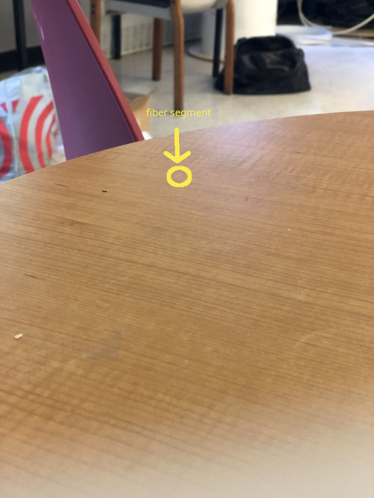
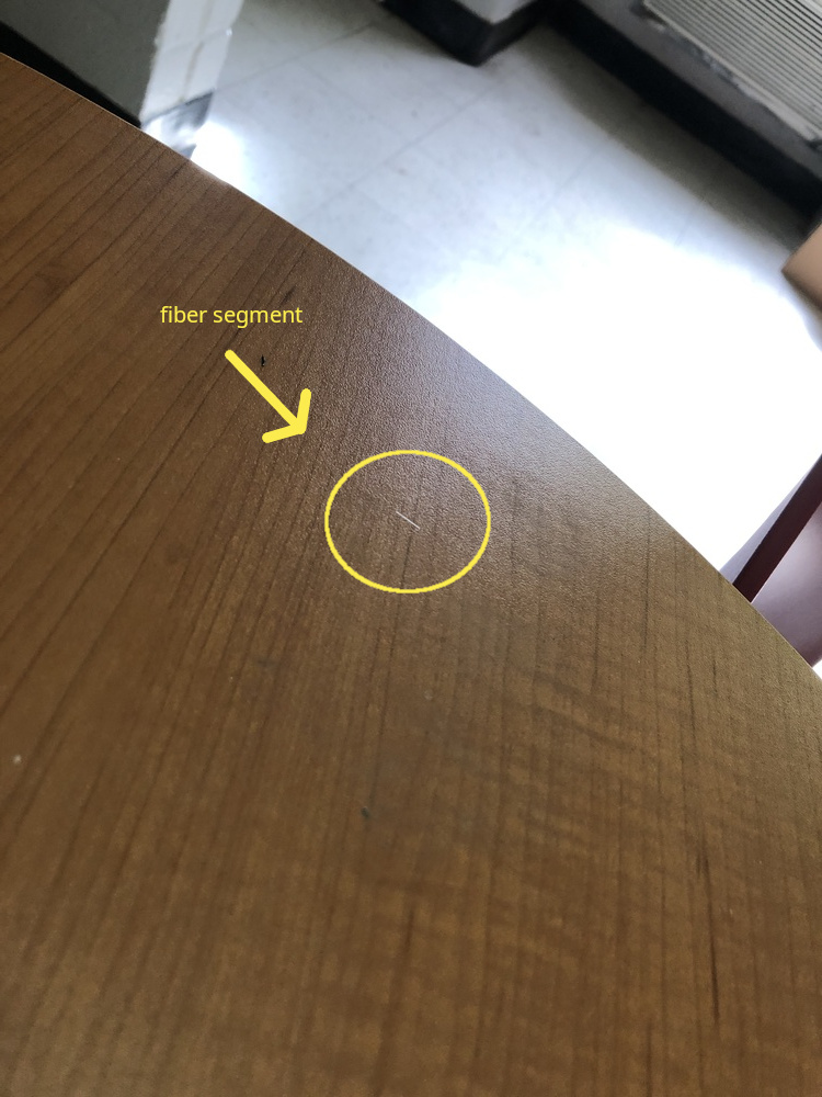
A piece of fiber scrap is a segment of bare fiber which gets created while cleaving or accidentally breaking bare fiber. Scraps can break down into smaller segments or into shards. They are the easier pieces to keep track of due to their length. If a scrap disapears, shining a flash light at different angles on a surface will produce a segment shaped glimmer if it hits a scrap.
As shown in the pictures bellow, the amount of light and angle at which it hits the scrap affects the visibility. Note that these are two different pieces of scrap, which were found by closely inspecting the surfaces using a flashlight.
2.2 Hazards:
There are two ways in which scraps are hazardous; pricking and snapping.
-
pricking
How:
Pricking can occur when the cable flicks back into shape and hits exposed skin, when attempting to grab scraps with bare hands, or when touching/sitting on a surface which happens to have unseen scrap(s) on it.
Consequence:
Pricking can lodge splinter or shards bellow the surface of the skin.
Mitigation:
PPE (rubber gloves, eye protection with side shields, coveralls, dark mat work area). -
snapping
How:
Snapping can either occur when the cable flicks back into shape or when bending the fiber too far when positioning the fiber on the cleaver or splicer.
Consequence:
Snapping can send both a scrap and shards flying; These can land on food, in the eyes, on the surface of the skin, and shards can be inhaled.
Mitigation:
No food or beavarages around, PPE (rubber gloves, eye protection with side shields, coveralls, dark mat work area, plexiglass sheet).
2.3 Potential consequences
-
Ingesting scraps can cause internal hemoraging.
-
Lodging scrap or shards bellow the skin will cause discomfort, and potentially cause infection.
-
Shards' potential consequences are addressed bellow.
3. Fiber Shards
3.1 Description:
Fiber shards are microscopic glass shrads; similar to fiberglass dust. They are nearly impossible to track due to their size; the smallest shards can be measured in micrometers (1 micrometer is 1/1000th of a millimeter).
3.2 Hazards:
- dispersion
How:
Due to their size, the smallest shards can be carried by air currents.
Consequence:
Shards can be inhaled, land on skin, eyes, clothes, food/beverage or nearby surface to be picked up later.
Mitigation:
The space needs to be well ventilated, no food or beavarages around, PPE (rubber gloves, eye protection (side shields), coveralls, dark mat work area, respirator designed for the hazard).
2.3 Potential consequences
-
Ingestion can cause inflamation and potentially internal hemoraging.
-
Shards in the eyes or on the surface of the skin can cause inflamation.
-
The Washington Department of Health claims that 1) Depending on the shards' size and shape, they may be biopersistant, 2) on the short term, inhaled shards will cause inflamation in the airways and exacerbate existing issues, and 3) on the long term, unlike for asbestos, lung disease rates of workers chronically exposed to fiberglass dust are "not consistently different from what is found in the United States general population". This source claims that this is due to the different structures of asbestos and fiberglass; that they break differently.
4. DOS AND DON'TS
DO:
- Clean up any cluter before handling fiber.
- Use PPE (e.g. eye protection or face visor, disposable coveralls, black rubber gloves ...).
- Wear dark clothes to spot scraps/shards more easily.
- Handle fiber over black, non-reflective surface.
- Handle fiber in a well lit and ventilated area.
- Pick up fiber fragments/scraps with tweezers (preferably rubber coated for better grip and lower risk of breakage).
- Frequently clean surfaces with adhesive tape (NOT a brush) to catch stray pieces. FOLD THE TAPE ONTO ITSELF BEFORE DISPOSING IT.
- Use tape to remove fiber coating from 3rd hole of stripping tool (since it may contain shards).
- Wash your hands after handling fiber.
- Dispose of fiber fragments and scraps in a suitable container; tape used to catch scapes should also go in that container.
- Follow systematic cleaning routine for your work area and all the equipment to avoid leaving scraps or shards behind.
DON'T:
- Touch fiber with bare hands.
- Touch your face after handling fiber.
- Blow dust or scaps off of a cleaver or fusion splicer, or any surface that looks dusty.
- Throw stripped material on the ground (stripping the coating can create shards).
- Look directly into plugged fiber to try to see lazer or infrared light ( infrared is invisible anyways).
- Eat or drink around fiber.
- If the segment is not visible, move your head around the cleaver or use a flashlight to make the glass shine; it may be on the top pad of the cleaver. DO NOT PICK UP THE CLEAVER AND FLIP IT UPSIDE DOWN; ESPECIALLY NOT ERRATICALLY. THERE IS NO REASON TO DO SO AND ONLY MAKES IT HARDER TO FIND THE SCRAP AS IT MAY FALL OFF.
5. RECAP
Hazard origins
Cleaving
-> scrap
-> shards
Cutting cable
-> shards
Snapping scrap
-> scrap
-> shards
Stripping jacket/cladding
-> shards
Hazards
Scrap
-> pricking
-> ingestion
Shards
-> inhalation
-> ingestion
-> skin, eye contact
Potential Health Consequences
Ingestion -> inflamation, internal hemorage
Inhalation -> airway inflamation
Pricking -> infection
Skin, eye contact -> inflamation
Bonus
Although risks are low for a few installs, over the long run, some installers may want to take more precautions. An extremely safe setup for the most risk averse of installers would be a DIY fume extractor. This setup is compact and mitigates all of the hazards mentioned in the previous sections.
The plexiglass walls contain any dust in a small area, the gloves protect the installer's skin and clothes, and the negative presure fan ensures proper ventilation. In addition, hooks and magnets can be used to keep some tools organized and permanently inside the container (e.g. stripping tool, tzeezers, alcohol pads...). In order to perform a splice near the ceiling, some mechanism needs to be used to strap the container atop a ladder (unless the installer considers a baker scaffolding affordable and convenient)
Equipment list:
- fume extractor ( < $200)
- 6 18*24 acrylic sheets + acrylic cement + small hinges OR large, clear plastic box (plastic box may not be as practical as custom acrylic box)
- 4 inch hole saw
- 4 inch pvc pipe
- plastic epoxy
- 2 worm clamps (for the gloves on the extractor)
- gooseneck arms with aligator clips
- nonslip pads
- arm-length gloves
- ventilation ( < $100)
- vaccum/fan with ~40ft 4 inch vent hose
- 4 worm clamps (2 for window adaptor to fan, 2 for fan to extractor)
- portable ac window adapter
6. Resources
- Health and Safety in Fiber Optics | UTEL
- Fiber Optic Safety Procedures
- Don't Ignore the Hazards Associated with Fiber Optics
- FOA Lecture 2: Safety When Working With Fiber Optics
- Top 10 Safety Rules for Fiber Optics
- WSDoH fiber safety
- IS FIBERGLASS A HEALTH HAZARD?
Nyc Mesh Fiber Background And Splicing Guide
NYC Mesh Fiber Background and Splicing Guide
These are notes collected by @JohnB from the fiber splicing class taught by Zach Giles at the NYC Mesh room on July 19, 2022. I took notes on my phone, so some of the information might be missing/inaccurate.
Theory
- Rule 1 is to not touch the bare fiber. Getting it dirty can impede transmissibility, and breaking it is very easy to do. If that happens, embedding it in a finger or clothing is easy to do, and it's so small, sharp, and hard to see that it is considered dangerous. It is after all a 9-micron shard of glass
- Decibels and fiber signal
- 0dB is considered "reference." For fiber and lasers, 1 milliwatt is this 0dB reference and all other decibel measurements are relative to this reference.
- Decibels are on a logarithmic scale. With every +3dB the power goes up by double, and for every -3dB the power goes down by half. For every +10dB, the power goes up by an order of magnitude, and for every -10dB, the power goes down by an order of magnitude.
- So if 0dB is 1mW, +3dB is 2mW, +6dB is 4mW, and in the opposite direction -3dB is 0.5mW, -10dB is .1mW, -20dB is .01mW, and so on. This will be important for a few reasons later
- (Background) The log scale is a result of the inverse square law of electromagnetic radiation, which basically says that a signal's power is cut in half for each unit of distance away from the source. If reference is 1 unit away and 1 power, moving to 2 units away will result in 1/4 power, moving to 4 units away will result in 1/16 power
- Fiber cable structure
- At the core is a glass fiber that runs continuously through the length of the cable. If it breaks at any point due to bending, the cable will not transmit data. NYC Mesh uses mostly 9-micron diameter glass fiber, which is "single-mode." Multi-mode fiber is 50 microns in diameter.
- Surrounding the glass core is the "cladding." This is another type of glass, but applied as a residue on the fiber. Since the cladding glass and fiber glass are slightly different, it acts as a sort of mirror surface. Light in the fiber that hits the edge will reflect back, ricocheting around. In essence, the cladding keeps the laser light inside the fiber.
- Surrounding the cladding is the "coating." This is plastic, and may be multicolored. This is a very minor form of stress relief. This also serves to protect the cladding and core from handling. If the core is broken due to over-stressing and is being tested with visible light, red light may shine through the coating where the break occurred.
- Surrounding the coating is a heavy duty "jacket," along with a Kevlar fabric line. This gives the cable the handling characteristics of a normal cable, allowing it to be pulled without stressing the core, and also allowing it to have more rigidity so bending does not have as much a chance of breaking the core. For most of NYC Mesh, the yellow jacket will contain a single fiber core and cladding within a white coating. In other setups, multiple fibers, each with a distinct color coating, may be bundled within a single jacket.
- All in all, this type of optical fiber cable may lose about 3dB per kilometer. Ignoring any signal loss from the connectors, if an input is 0dB/1mW, at the end of a 1 kilometer fiber cable, a -3dB/0.5mW signal would be received.
- Fiber cable connectors
- NYC Mesh does not terminate fiber cables. Rather, pre-terminated cables are purchased, or connectors are purchased with "pigtails" that allow for easy splicing to unterminated fiber.
- Fiber cables come in a variety of different connectors, but the main form factors and types used by NYC Mesh are SC and LC connectors.
- SC connectors are predominantly used due to their durability, and are the connector of choice at Grand Street
- LC connectors are smaller and more efficient (size-wise or speed-wise? I'm not sure), but are more finicky. For this reason, they are used mostly in data centers where handling is less important.
- Connectors are just methods of handling and connecting the bare fiber, so the bare fiber actually sticks out of the end of the connector.
- The bare fiber is polished on the end, and the polish follows a variety of different standards that will be mentioned later. If two connectors are coupled together, the polish method must match.
- The polish method can't be determined just by looking at it, so the connector's color convey the polish type. Thus, the SC connector might be green to represent an angled polish, and would be called an APC connector (Angled Physical Contact). The SC connector might also be blue, representing a rounded polish, and is called a UPC connector (Ultra Physical Contact)
- Connector polish methods
- The bare fiber at the end of the connector is polished for efficiency reasons. If left raw and flat, the cable will be inefficient.
- Inefficiency is a result of attenuation/backscatter. Light from one end of the cable reaching the opposite end and encountering a flat fiber end would hit it head on and bounce back toward the origin. This is able to be measured in Decibels, and comes in at -30dB reflected back to the origin. So if the input signal was -8dB, the backscatter with a flat connector would be -38dB. This is known as Optical Return Loss, or ORL, or attenuation.
- Polishing the end can reduce the Decibel count and therefore optimize the signal.
- A blue UPC connector has a gentle bevel polish and its ORL/attenuation is -55dB, which is already 20dB or 100x better than the -30dB of the flat connector
- A green APC connector has an angled bevel polish, meaning it's asymmetric. This is fantastic for ORL/attenuation, giving it a -65dB rating. However, couplers and connections to other cables/connectors must have correct orientation. APC connectors have keys on them to ensure orientation is correct.
- Fiber Splitters
- A splitter can be used to duplicate a single input fiber signal into many duplicate signals.
- There is a cost to splitting, namely in the form of signal loss/attenuation. 10dB (?) is a common amount of attenuation to see for a signal going through a splitter.
- NYC Mesh at Grand Street uses 8-way splitters with 10dB loss. If an input signal is +6db/4mW and goes through the splitter, the output signal level of each of the 8 splitter outputs would be -4dB, or a little less than 0.5mW.
- Since each of the different connections of a splitter would be shooting their light into a shared fiber, they can interfere with one another's signals. To manage this, they take turns at set intervals to transmit their separate information. These windows of time are passed along from connection to connection evenly, known as a "round-robin" strategy. This overall grand scheme of figuring out who goes when, and for how long, is known as GPON
- OLT and in-unit boxes
- The OLT is the rack-mounted hardware and is the primary origin of the fiber installation. It has a number of ports, each outputting a +3dB/2mW signal. It expects a number of splitters to be connected in series on each port, so the stronger-than-reference signal is to compensate for the loss at each splitter. This way, the end client can still get a usable level of signal
- NYC Mesh uses in-apartment client boxes that need a signal of -8dB to -28dB. Plugged directly into the OLT, the signal would be too strong for the client box to handle. BUT after two splitters, the +3dB signal would be -17dB, and with a couple cables in between the signal might be -23dB. This is perfect for the client, AND means that two tiers of splitters can be used. This gives one OLT port the ability to split 8 times, and then each of those 8 additional times, or 64 client boxes to a single OLT port
- This works great for Grand Street, where there are 7-floor apartment buildings with 6 apartments per floor. Each building gets a splitter in the basement, with one cable going to each floor. Each floor then gets its own splitter, yielding 6 to 8 connections per floor. One OLT port can then serve an entire apartment building
Fiber Splicing Guide
- Equipment
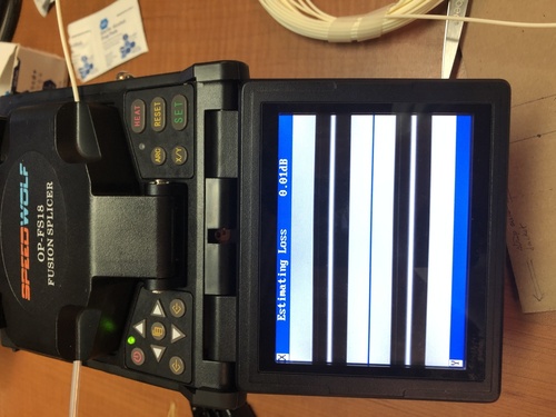
- SPEEDWOLF Optical Fiber Fusion Splicer, OP-FS18 - This has the actual splicing bits, as well as a heater section to heat-shrink and stabilize the fused section. It has an X-axis and Y-axis camera so it can automatically align the two fiber cores to be spliced, and then two electrodes to clean and then fuse the fibers together.
- SPEEDWOLF Fiber Optic Cleaver, OFC-21 - The fiber core is placed inside the cleaver to get a perfectly flat end, ready for fusing
- Fiber Optic Stripper - Jonard JIC-375 is an example. One with three holes is desired, optimized for each layer of the fiber cable: biggest and first is the plastic jacket, middle and second is the plastic coating, and last and third is the scraper for the cladding
- Kevlar Scissors - Jonard JIC-186 is an example. These are super sharp and made for cutting the extremely-durable Kevlar inside a fiber cable. We also used them to slice the entire fiber cable, but I'm not sure if that's only because a regular wire cutter was missing
- Tweezers - used to grab fiber core fragments, especially fragments left behind in the cleaver
- Alcohol wipes - used after scraping the cladding off to get the fiber core squeaky clean and ready for fusion
- Tape - Masking or Painter's tape works, and is only used to more easily pick up and collect fiber fragments for safe disposal later
- Splice Protection Heat Shrink Sleeves - heat shrink, but with an added metal wire inside for rigidity, used to stabilize the splice after fusing
- OTDR Fiber Tester - D YEDEMC Mini-Pro is an example - an expensive, powerful, multi-purpose fiber optic tester. Visible light testing, 1310nm signal loss testing, length testing, and more.
- Step 1: Cable Prep
- Start with a raw fiber cable sliced in half with wire cutters. Use the widest fiber optic stripper hole to remove 5-6 inches of the yellow outer jacket, leaving behind the white coating+cladding+core and a tangle of Kevlar
- Use the Kevlar scissors to trim away as much of the kevlar as possible
- Use the second hole of the fiber optic stripper to remove 2-3 inches of the white coating. Due to friction, removing it all at once is not possible. Start at the tip and remove 1cm at a time, until the full length is achieved
- Use the third hole of the fiber optic stripper to remove the cladding from the fiber core. A white residue should appear on the strippers. Repeat this 2-3x to ensure all the cladding is removed
- Pinch the bare fiber optic core with an alcohol wipe and wipe from where the white coating first becomes exposed all the way to the end. When going over the fiber optic core, it should sound "squeaky" clean. Repeat 2x. Do not touch the fiber core after this.
- The cable is now ready for cleaving
- NOTE: The NYC Mesh sleeves are 60mm in length. That means that one of the two halves to be cleaved must have an extra 60mm of yellow jacket removed, relative to the other, in order to fit the sleeve during splicing.
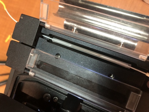
- Step 2: Cleaving
- Open the two doors of the cleaver. One on the left holds the fiber core plus coating in place, and one on the right covers the blade wheel
- Push the blade wheel assembly from the back of the cleaver forwards towards you, towards the front side of the cleaver. When the door is closed, it will only move front to back, so this is prepping it for a later cut
- Place the fiber core and coating across the cleaver in the narrow slot. The fiber core needs cross over the blade and rest on the two black pads on either side. If not, the right door cannot trap it in place and the cut cannot be made. The cleaver has markings in millimeters for how much bare fiber core will remain after the cleave. I aimed to have the white coating begin somewhere under the left door. When in place, close the left door to hold it in place.
- Close the right door
- Push the blade assembly towards the back, performing the cleave
- Open the right door carefully and use the tweezers to grab and dispose of the fiber fragment left behind. It may stick to one of the black pads on the right door's right side
- Open the left door to free the coating and fiber core. Do not touch the fiber core.
- Once cleaved, the fiber is ready for placement in the splicer. Move it to the splicer in the next step
- NOTE: The NYC Mesh sleeves are 60mm in length. That means that each of the two halves to be cleaved have to have less than 30mm of exposed fiber core after cleaving. However, if the fiber core is cut too short and the yellow jacket is not cut back enough, the primary door of the splicer might not close in the next step.
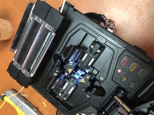
- Step 3: Splicing
- Open the primary door of the splicer, and then open the left and right doors underneath.
- With the splicer on, press the RESET button to move it into the starting position. If RESET is not pressed and the X and Y axis cameras are on, the splicer is in SET mode and still needs RESET pressed. RESET mode will take the splicer to a menu outlining the settings to be used for splicing.
- Also press HEAT to start pre-warming the heat shrink channel for a later step
- Imagine an up/down line in between the two metal pointy electrodes of the splicer. This marks the center line. Place the fiber in a perpendicular orientation to this line on either the left or right side, taking care not to cross the center line. Get the end of the fiber as close as possible but not crossing this imaginary line. The alignment motors can only move forward, so if the end were to cross, the splicing could not occur. The fiber core should sit within the crook of two blue V-shaped holders, and the white part will likely be under the left door closure area. The yellow jacket also needs to be beyond the edge of the splicer's primary door, or the door will not close. Once the fiber, coating, and jacket are all in place, close the left door to hold it.
- Repeat Step 1 for the other fiber. NOTE that at least one half needs the sleeve slid onto it before splicing. The yellow jacket is bigger than the sleeve, so it will need to be cut back further so the sleeve and jacket can be pushed out of the way of the splicer's primary door.
- Repeat Step 2 for the other fiber, cleaving it and preparing it for splicing
- Repeat Step 3 up to this point, placing the fiber on the right half of the splicer without crossing the imaginary center line. Close the right door
- Close the primary door of the splicer
- Press the SET button to begin the splicing process. First it will move the ends of each fiber core into view of the cameras. Each should appear flat and cylindrical and as "clean" as possible. The splicer will first "zap" the ends to clean them further, and will then run a longer fusion process to merge the two fibers. Once visible again, a single uninterrupted fiber should be seen on the camera views.
- Step 4: Sleeving
- Open the primary door of the splicer, and then open the door on the side with the sleeve.
- Grasp the fiber cable jacket/sleeve on the freed side, and then open the opposite side's door and grab that side as well
- Move the sleeve to cover the spliced area. Be VERY careful not to bend or shift the two halves of the cable, as the fiber cores are barely held together at this point and can snap/shear easily. The sleeve must fully cover the exposed fiber core, spanning from the white coating on one side to the white coating on the other. If it does not reach, the splice is invalid, and the full cutting/stripping/cleaning/cleaving process will need to be re-done.
- Open the left, right, and clear center doors of the heat shrink heater portion of the splicer
- Move the now-aligned sleeve plus the two cable halves into the heater. Close the heater doors, ensuring that that fiber cables sit in the U-shaped channels on each side.
- Press the HEAT button on the splicer to perform the heat-shrinking operation. It will begin heating
- Meanwhile, close the left/right/primary splicer doors and press RESET to prepare the splicer for the next run.
- Once the heat shrink operation is done, the splicer will beep. Open the doors and carefully move the cable to the cooling tray. Leaving it in the heater too long may cause it to cool and stick to the heater, making removal difficult.
- NOTE: Ideally, regular black heat shrink would be added to the cable as well and fully cover the coating, going from yellow jacket to yellow jacket.
- Step 5: Testing
- First, a visual check can be done using the OTDR. Set it into VFL mode, which emits a 650nm red light. Look for "light leaks" along the cable's length, especially around the splice. If red light can be seen, that means it's not being efficiently reflected down the length of the cable, and could indicate signal loss
- Next, an attenuation check can be performed. the OTDR to OTDR mode, which will generate a graph with distance/position on the X axis and attenuation on the Y axis. Since the OTDR is outputting a known signal strength, the exact loss at any point can be measured. This can be done by emitting a very short-duration pulse and then switching into listening mode to evaluate when and how strong the backscatter returns.
- Next, an overall signal loss check can be performed. Set the OTDR to output a 1mW 1310nm signal, and plug the other end either into the OTDR receive jack, or a second strength tester's jack. The dB of the returned signal indicates how much loss there was simply from entering and exiting the newly-created cable. -3dB to -4dB is about what's expected in a well-made cable, after loss from the connectors plus the cable length. If -70dBm is being read, the cable either has a break, or the output from the OTDR is not yet emitting.
Resources
- OTDR tester https://www.amazon.com/YEDEMC-Mini-Pro-Mulit-Function-5m-60Km-Dynamic/dp/B07Z1XCRBF
- Heat shrink tubing sleeves https://www.amazon.com/Shrinkable-Optical-Fusion-Splice-Protection/dp/B01FR0ZTNA
- Fiber Optic stripper tool https://www.amazon.com/Jonard-Tools-Fiber-Optic-Stripper/dp/B006962CUK
- Fiber Optic Fusion Splicer https://www.amazon.com/SPEEDWOLF-Alignment-Portable-Splicing-6XElectrodes/dp/B07RKVXZ5R
- Article on different connector types https://www.fiber-optic-solutions.com/evolution-of-flat-pc-upc-and-apc-fiber-connectors.html
- Article on different components in a fiber cable http://labman.phys.utk.edu/phys222core/modules/m7/optical-fibers.html
- Article and calculator to convert decibels to milliwatts https://www.rapidtables.com/convert/power/dBm_to_mW.html
- Article on the inverse square law https://energyeducation.ca/encyclopedia/Inverse_square_law
- Article referencing the 9 micron size of single-mode fiber https://www.thefoa.org/tech/ref/basic/fiber.html
Fiber Splicing Tutorial
1. Intro
These instructions assume only the required tools are used, and minimal precautions taken; no assumptions about safety equipment or convenient tools.
There are 7 procedures to perform in the splicing process; roughly in the following order:
- setup
- strip cable to bare fiber
- cleave bare fiber
- fuse
- test
- apply heat to shrink sleeve and tube
- clean up
Procedures 2 and 3 will be performed twice; once for each of the two cables. However, one side will need to have more outer jacket stripped off to make room for the shrink sleeve; to move it out of the splicer. The side on which the sleeve will be is refered to as Side With Sleeve (SWS), and the other as Side WithOut Sleeve (SWOS). Note that the sequence will be strip SWS, cleave SWS, position SWS in splicer, AND THEN strip SWOS, cleave SWOS and position SWOS in splicer. That sequence minimizes the risks of mishandling each cable, which could result in one or both of 1) a fiber splinter and 2) breaking the bare fiber; either of which could require starting the process over for that cable since even if the bare fiber did not break, if it has been cleaved, poking any surface could ruin the cut.
During procedure 4, the fibers may need to be repositioned multiple times to align the fiber correctly. This is because, as noted in the fiber safety page (detail 3 to consider), the cable is curved; making this part challenging since the cable needs to be positioned straight and precisely.
Procedure 5 is performed before 6 since it would be a waste of time and resources to shrink the shrink sleeve and the shrink tube if the splice needs to be redone.
2. Steps with pictures
Bellow are pictures taken through out the splicing process. (the ordering numbers come from the detailed list in the next section)
- Stripping the outer jacket of SWS:
- Stripping the inner jacket of SWS:
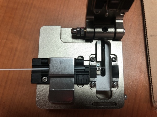
- Positioning the stripped SWS in the cleaver:
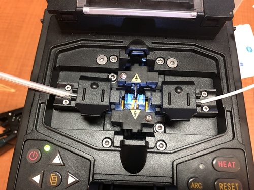
- Positioning the cleaved SWS in the splicer:

16-17) Stripping the outer and inner jackets of SWOS:
- Positioning the cleaved SWOS in the splicer:
- Read splicer screen to view the quality of the splice and an estimate of signal loss:
- Test splice:

- Place shrink sleeve over the fused, bare fiber and move the whole to the splicer's heating compartment to shrink the sleeve:
- Verify that the sleeve has in fact shrunk (may need to heat 1-3 times):
The result:
3. Detailed list of steps
3.1 Prep
-
prepare all the equipment required; includes tools and any PPE.
-
cut shrink tube (20cm).
-
prepare shrink sleeve.
-
mark location to cut on cable from each side.
-
slide shrink tube down either cable.
3.2 Begin Process
-
Take a cable from either side; this cable will be the side with the shrink sleeve (SWS), the other will be the side with out the sleeve (SWOS).
-
Strip outer jacket of SWS (12cm) and cut kevlar.
-
Slide shrink sleeve over inner jacket of SWS.
-
Strip inner jacket of SWS (2cm) into sharps container.
-
Strip cladding of SWS into sharps container and apply alcohol pad.
-
Cleave SWS.
-
Use tweezers to pick up fiber fragment and drop into sharps container; verify that the segment was indeed in the tweezers all the way to the sharps container, and that it fell in the container before putting the tweezers down.
-
Position SWS in fusion splicer.
-
Use tape to clean any potential glass pieces around and between cleaver and sharps container (if they are not moved before cleaving the other side, this can be done after the second cable is cleaved).
-
Take SWOS.
-
Strip outer jacket of SWOS (5cm) and cut kevlar.
-
Strip inner jacket of SWOS (2cm).
-
Strip cladding of SWOS and apply alcohol pad.
-
Cleave SWOS.
-
Use tweezers to pick up fiber fragment and drop into sharps container; verify that the segment was indeed in the tweezer all the way to the sharps container, and that it fell in the container before putting the tweezers down.
-
Clamp SWOS and position it in fusion splicer (clamp to reduce movement when removing the splicer clamp; due to cable curve).
-
Use tape to clean any potential glass pieces around and between cleaver and sharps container.
-
Fuse cables.
-
Connect cable ends to testing devices and test signal loss.
-
Carefully release each cable from splicer clamps.
-
Slide shrink sleeve over exposed fiber and place in splicer's heating compartment; sleeve should cover each side roughly 3cm from joint.
-
Heat 2-3 times.
-
Slide shrink tube over shrunk sleeve; the shrink tube must leave no inner jacket exposed.
-
Shrink shrink tube with lighter while adjusting grip to ensure the shrink tube cools straight; may consider using solder clamps for this step.
3.3 Clean and pack up
-
Use tape to clean each piece of equipment and put them back in toolbox
-
Fold tape in half, sticky side in, to trap any potential glass pieces.
-
Dispose of tape and pack up the rest of equipment.
4. Template
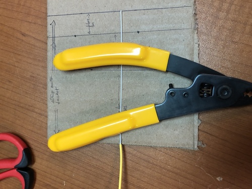
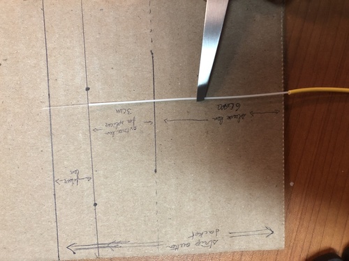
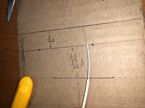
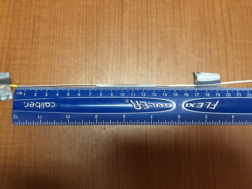
In order to strip jackets quickly and precisely the installer should make a template, such as the one shown bellow.
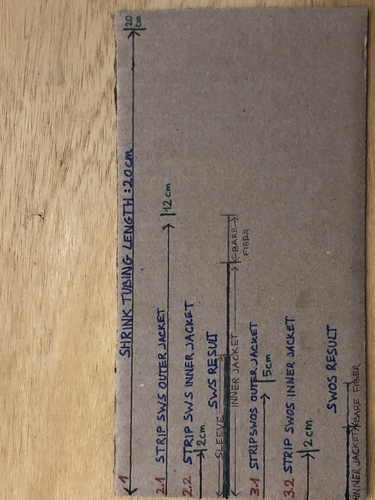
Note that the template in the picture is crowded to illustrate the instructions in section 3; a color coded stick may be easier to work with.
Stick template example (1 dash = 1cm):
< - - - -0- - - - >< -1- >< -2- - >< - - -3- - - - >< - - - -4- - - - >
0: no color -> 8cm; Space for palm of hand.
1: green -> 2cm; Strip inner jacket of both SWS and SWOS.
2: white -> 3cm; green + white = 5cm to strip SWOS outer jacket.
3: yellow -> 7cm; green + white + yellow = 12cm to strip SWS outer jacket.
4: black -> 8cm; green + white + yellow + black = 20cm to cut shrink tubing.
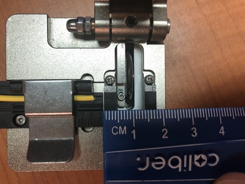
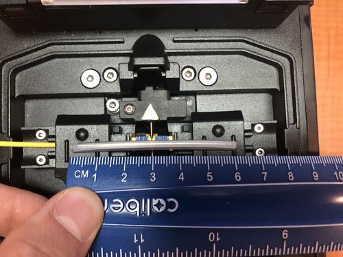
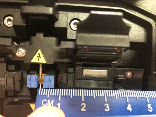
The following pictures show the measurements used to determine the lengths. Note that template lengths are longer to leave ample room for errors.
The pictures show that:
- The outer edges of the cleaver pads are 1.8cm apart; this is the minimum length of bare fiber required for proper grip to cleave.
- The cleaver will leave about 1.5cm of bare fiber on each cable -> the 6cm shrink sleeve will cover about 3cm of bare fiber and 3cm of inner jacket.
- The shrink sleeve on SWS needs to be >4cm away from the splicer needles to clear the clamp (includes 1.5cm of bare fiber) -> 10cm of inner jacket on top of the 1.5cm of bare fiber.
- The resulting gap (shown in the result picture in section 2), from outer jacket to outer jacket, which needs to be wrapped in shrink tubing is about 16cm -> cut 20cm of unshrunk shrink tubing.
Fiber to the Apartment
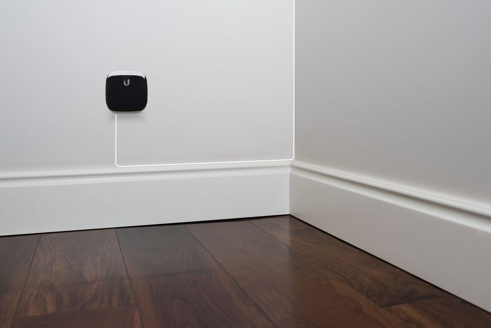
The first step is to screw the ONT into the wall in a convenient place using drywall achors. The ONT we are currently using is the Ubiquiti UF-WiFi6-US
Only use white fiber inside apartments, never yellow or any other color. This is to better blend in with the wall. We have custom made 3mm white fiber with termination at one end.
Once the ONT is screwed into the wall, plug in the terminated end of the white fiber. Now you are ready to run the fiber to the exit point (usually above the front door). You first run the fiber down to the top of the baseboard and then along to the nearest corner, attaching it to the wall with silicone or staples. You run the cable up the corner to the ceiling and follow along the corner of the ceiling to the exit point using silicone or staples along the way.
As always with fiber, don't do any hard bends! Let the fiber curve around corners.
There is no loose fiber in the apartment, just a service loop above the door. All the fiber is locked down with silicone or staples the whole way. Any loose fiber will result in service calls. Excess fiber is pulled back into the apartment and left as a service loop above the door. Trim the yellow raceway fiber down before splicing so it one foot from the entry point. Use excess white fiber to enable the splice.
At the exit point you drill a small hole (6mm?) and feed the unterminated end of the fiber through to the raceway. The fiber will be spliced outside of the apartment either with a fusion splicer or with a mechanical splice. The hole must be sealed after you're finished!
The new ONT has a built in router so install it near a power outlet and you are done. You will need to log into the OLT to configure the router
The older model ONT is powered by connecting it to a POE injector, and connecting the data port to a TP-Link/Archer home router.
Support
[to be expanded!]
Fiber support is fairly straightforward. First do the usual test of the wifi router to eliminate that as the problem. Next test the signal going into the ONT by unplugging the connector and connecting it to your meter.
Test db of signal using an OTDR or optical power meter (OPM). The signal should be between -22db to -10db. Less than -24db and the signal is too weak. -8db is the highest limit that will work.
If the signal is outside of the range of -22 to -10 you need to look for where signal loss is occurring. This is typically the splice in the raceway or damaged fiber that has been bent.
Light fiber with red test signal using the OPM or OTDR. This is done from the hallway access box.
Look for loss along the way, especially in the raceway splice. Redo splice if signal loss is there. If the cable is damaged elsewhere, splice around the damage.
Fiber install guidelines
In order to avoid problems with fiber install quality, the following guidelines should be followed:
- Boxes should be located near floor or with long enough winder boxes to enable work on the floor.
- No ladders should be necessary for maintenance/splicing.
- No ladders should be necessary for maintenance/splicing.
- Cable should not be jammed in distribution boxes.
- All cables/ports should be labeled.
- All work should be centrally documented (Mesh or contractors).
- All fibers in a cable should be terminated initially. Never leave fibers unterminated.